IA-204 SERIES OF IN-WALL AMPLIFIERS INSTALLATION MANUAL ©Emtech Electronics, Inc. 1126 N.
IMPORTANT SAFETY INFORMATION FOR YOUR SAFETY To ensure safe operation, all connections between the power supply and the mains should be made by a qualified person, and approved by local government inspectors. The fact that the equipment operates satisfactorily does not imply that the power point is properly grounded and that the installation is completely safe. For your safety, we recommend that the mains connections be made only by a licensed electrician.
INTRODUCTION Thank you for choosing an Emtech Electronics Product. The IA-204 series of In-Wall Amplifiers are the intelligent solution for single and multi-room sound reinforcement applications were rack space does not exist for a sound system. The IA-204 system requires no special training for your personnel or guests. There are no confusing, elaborate programming sequences necessary to adapt the system to different room configurations. Room combining is achieved effortlessly with the flip of a switch.
Operating the IA-204 series of in-wall amplifiers is simple. Just follow these three steps: 1. 2. 3. Turn the POWER switch to the ON position (LED will illuminate). Set your input source on INPUT 1 or INPUT 2 to either mic or line using the switches. Adjust VOLUME control for the desired sound output.
IA-204 Location • • The suggested mounting height for the IA-204 is approximately 48” – 66” from the floor. The mounting location for the IA-204 depends upon many factors, such as the room layout, input location, distance to the power supply, etc. Mounting • • The IA-204 fits into a common 4 gang deep masonry electrical box (RACO 698 or equivalent). Four painted mounting screws (6-32 x 1” flathead Phillips) are provided to secure the IA-204.
NOTE - This information is applicable only to the power supplies available from Emtech Electronics. If you choose to use a different power supply, please follow the manufacturers instructions. Location • A central location is most desirable for the power supply. • Keep the distances between each IA-204 and the power supply as short as possible.
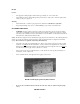
CONNECTING THE IA-204 WIRING • • • • • • • • Microphone and line input signals require shielded cables. If using the RCM-42B Room Combining Matrix, use shielded cables to connect the RETURN and SEND between the IA-204 and RCM-42B. Each IA-204 is shipped with jumpers on the seven pin orange screw terminal connector between pins 4 and 6, and 5 and 7. These need to be removed if you are using the RCM42B. These jumpers are necessary to connect the SEND and RETURN when no RCM-42B is connected.
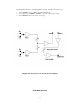
IA-204P Figure 3 shows the screw terminal connections for the IA-204P. J1 10 PIN CONNECTOR • • • • • • • • • • • PIN 1 Mic 1 and Line 1 ground PIN 2 Mic 1 + input PIN 3 Mic 1 – input PIN 4 Line 1 + input PIN 5 Line 1 – input PIN 6 Mic 2 and Line 2 ground PIN 7 Mic 2 + input PIN 8 Mic 2 – input PIN 9 Line 2 + input PIN 10 Line 2 – input Line level signals can be balanced or unbalanced.
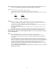
Figure 4 shows the screw terminal connections for the IA-204R. J1 • 10 PIN CONNECTOR Same as IA-204P J2 • • • • • • • 7 PIN CONNECTOR PIN 1 Power supply ground PIN 2 Power Supply + input 24 vdc PIN 3 No connection PIN 4 SendPIN 5 Send + PIN 6 Return – PIN 7 Return + J3 For future expansion. J4 3 PIN WHITE CONNECTOR: This connector is for the Emtech T-70V transformer connector. If you do not order this transformer, a factory installed jumper is placed between pins 1 and 3.
NOTE! When using the IA-204S with the RCM-42B Room Combining Matrix, you will need a single-pole, doublethrow center off switch to provide for control of the Room Combining feature. This switch connects to the same Room Combining channel as the IA-204S. Figure 5 shows the screw terminal connections for the IA-204S.
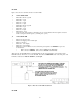
Step 1: Draw room speaker layout.
Step 2: Circle desired Zone A and Zone B speakers. Step 3: Connect speakers. Example below Zone A or Zone B (Shaded) Figure 7. Laying out Head Table Speaker Zones TESTING & TROUBLESHOOTING POWER SUPPLY • The power supply voltage (24 VDC) and polarity should be checked at the connector of each IA-204 and RCM-42B prior to connecting and turning the power on. SPEAKERS • Speakers should be tested for proper phasing (polarity) and correct wiring configuration with a multi-meter.
• If you are using the IA-204R with the ROOM MIXING switch, check the operation of the ROOM MIXING switch by setting it to the GROUP A or GROUP B position on any two or more IA-204’s that are connected to the RCM-42B and verify that they are sharing program material. IA-204S • If you are testing the IA-204S, and have two speaker zones pre-wired, check the speaker zones by switching the SPEAKERS switch to the A OFF, ON, and B OFF positions and verifying the results.
Block Diagram of the RCM-42B RCM-42B ROOM COMBINING MATRIX FEATURES • • • • • • Allows up to four IA-204’s to share program material. Provides two combining busses for your IA-204 system. Digitally controlled switching for ease of operation. Uses screw terminal connectors for fast and reliable installation. Silk screened label for error free installation. When in use, allows the power amplifier section of grouped IA-204’s to work as “slave” amplifiers, and allows all mic/line inputs to act as “masters”.
• • • Mount the RCM-42B in a convenient location, such as next to the power supply. There are 4 screw terminal connectors on the RCM-42B. Each of these connectors is labeled for a specific room, room one through room four. The room one connector has two extra pins for the power supply inputs.
• • • • • • The INPUT – and INPUT + terminals are connected to the SEND – and SEND + wires from the IA-204. The OUTPUT – and OUTPUT + terminals are connected to the RETURN – and RETURN + wires from the IA-204. The cables connecting the inputs and outputs between the IA-204 and the RCM-42B must be shielded. Terminate the shielding at the RCM-42B only! Each orange connector on the RCM-42B has two terminals labeled GROUND for this purpose. The BUSS A and BUSS B pins connect directly to the IA-204R.
SPECIFICATIONS Power Out……………………………………………………… ………………………….20 Watts RMS into 8 ohms. ………………………………………………………………………………………………25 Watts RMS into 4 ohms. Mic Input Sensitivity.………………………………………………………………………………………………5 mV. Line Input Sensitivity…………………………………………………………………………………………….100 mV. Frequency Response…………………………………………………………………………………± 3dB 30 to 18Khz. Distortion…………………………………………………………………………………………………Less than .04%. Mic Input Impedance…………………………………………………………………………………………….3 k ohms.
SERVICE In the unlikely event that service should ever be required on your IA-204, first perform all of the checks in the troubleshooting section of this manual. If the problem still persists, the IA-204 will have to be removed for servicing. • • • • • Make sure that the IA-204 power switch is turned off. Loosen and remove the 4 screws that attach the unit to the 3-gang electrical box.