
Owner's manual


8
IA-204P
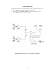
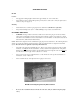
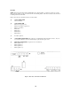
Figure 3 shows the screw terminal connections for the IA-204P.
J1 10 PIN CONNECTOR
• PIN 1 Mic 1 and Line 1 ground
• PIN 2 Mic 1 + input
• PIN 3 Mic 1 – input
• PIN 4 Line 1 + input
• PIN 5 Line 1 – input
• PIN 6 Mic 2 and Line 2 ground
• PIN 7 Mic 2 + input
• PIN 8 Mic 2 – input
• PIN 9 Line 2 + input
• PIN 10 Line 2 – input
• Line level signals can be balanced or unbalanced. If you connect unbalanced line level signals, connect the
shield to both ground and the negative (-) terminal (pin 5 or pin 8).
J2 7 PIN CONNECTOR
• PIN 1 Power supply ground
• PIN 2 Power Supply positive 24 VDC input
• PIN 3 No connection
• PIN 4 Send - (Line Output)
• PIN 5 Send + (Line Output)
• PINS 6 and 7. The IA-204P does not have an internal power amplifier, so the RETURN - + pins serve
another function.
• PIN 6 connects to GROUP A. (This connects to BUSS A on the RCM-42B)
• PIN 7 connects to GROUP B. (This connects to BUSS B on the RCM-42B)
When using the optional RCM-42B Room Combining Matrix, the Room Combining Buss control signals from the
RCM-42B connect to Pins 6 and 7 of J2 on the IA-204R. This allows the ROOM MIX switch on the front panel of the
IA-204R to switch between LOCAL, GROUP A, and Group B.
Figure 3. Rear View of IA-204P Circuit Board