Installation & Programming Guide EMTouch™ Electronic Deadbolt Locksets ASSA ABLOY, the global leader in door opening solutions
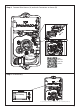
What’s in the Box 4b 4d 4a 4c 2 5 1 3 6 4 8 7 9 6 ITEM NO. QTY.
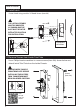
Preparation 1. Door Prep 2 3/8” or 2 3/4” Backset 1/8” Deep 2 1/4” 2 1/8” Diameter Bore 1“ 1” Diameter Edge Bore 2. Door Jamb Prep Step 1: Fasten Security Plate using two #10 x 3” Wood Screws (item #9). Step 2: Fasten Strike Plate using two #8 x 3/4” Wood Screws (item #6).
How to Install 1. Install Latch Fasten Latch using two #8 x 3/4” Wood Screws (item #6). ! THE LATCH ASSEMBLY MUST BE ORIENTED AS SHOWN AND THE BOLT MUST BE IN THE RETRACTED POSITION FOR INSTALLATION. Crosshairs at bottom. 2. Remove Screws from Inside Trim Plate Use a Phillips head screwdriver to remove screws (item #4c) shown below and detach Inside Trim Plate from the Inside Chassis. ! REMOVE INSIDE CHASSIS FROM TRIM PLATE BEFORE INSTALLING THE OUTSIDE TRIM. THUMBTURN MUST BE IN UNLOCKED POSITION.
3. Install Outside Trim Plate Assembly Position the Outside Trim Plate Assembly through the bore hole. ! Feed wire harness through the bore hole. ONCE POSITIONED, OUTSIDE TRIM PLATE ASSEMBLY REQUIRES SUPPORT. Scan this QR code for details. Fit Flat Shaft through latch. Flat Shaft must be in vertical position for installation. 4. Install Inside Chassis Step 1: Confirm the position of Flat Shaft. ! HOLE FOR FLAT SHAFT MUST BE IN VERTICAL POSITION FOR INSTALLATION. √ Correct for Installation.
4. Install Inside Chassis Step 2: Feed the Wire Harness through Inside Chassis. Step 3: Fasten Inside Chassis using two #8-32 x 11/2” Flat Head Machine Screws (item #5). ! CHECK ALIGNMENT BEFORE FULLY TIGHTENING SCREWS.
Step 4: Connect Wire Harness (A) and tuck Connectors as shown (B). A B Scan this QR code for details. Step 5: Install Battery. 9V Battery For optimal performance, always use a good quality battery.
5. Install Inside Trim Plate Fasten Inside Trim Plate using two #8-32 x 3/8” Flat Head Machine Screws (item #4c). ! USER CODES ARE LOCATED ON THE INSIDE TRIM PLATE & ON PAGE 11. Correct for installation Inside Incorrect for installation *Unlocked Locked *Unlocked position is required for installation and removal of the Inside Trim Plate Assembly. ! THUMBTURN MUST BE IN UNLOCKED POSITION FOR INSTALLATION.
How to Use Your Lock is Ready to Use Your Emtek lock is shipped with two 4-digit user codes and a 6-digit programming code. These codes are randomly generated at the factory. (Turn to next page for Programming Instructions.) To Unlock: 1. Press EMTEK key or touch 3 fingers across screen. 2. Enter 4-digit user codes. (See sticker located on the inside trim plate or on page 11). 1 2 3 3. Rotate Thumbturn. To Lock: 1 Option 1 1. Press EMTEK key. 2. Rotate Thumbturn. Option 2 2 1.
How to Program Programming Your Lock In order to perform each of the following six functions, the lock must first be placed in Programming Mode: 1. 2. 3. 4. 5.
Keypad Operation - Beeper & LED Indicators Function Valid Code Invalid Code/Access Denied* Lock-Out Mode Error Indicators • 1 short beep, EMTEK button flashes Green.
Scan for how to install videos. ASSA ABLOY is the global leader in door opening solutions, dedicated to satisfying end-user needs for security, safety and convenience. Copyright © 2012, Emtek Products, Inc. an ASSA ABLOY Group company. All rights reserved. Reproduction in whole or in part without the express written permission of Emtek Products, Inc. is prohibited.