Emulex Model 375 SAN Storage Switch For Apple Computer Users 00041392-002 Rev.
EMULEX MODEL 375 SAN STORAGE SWITCH USER ’S GUIDE © 2004 Emulex Corporation. All rights reserved. Emulex and Vixel are registered trademarks, and InSpeed and FibreSpy are trademarks, of Emulex Corporation. All other brand or product names referenced herein are trademarks or registered trademarks of their respective companies or organizations. EMULEX CORPORATION PART NUMBER 00041392-002 REV.
EMULEX MODEL 375 SAN STORAGE SWITCH USER ’S GUIDE TABLE OF CONTENTS Table of Contents Table of Contents ...................................................................................ii Chapter 1: Introduction ....................................................................................... 1 Chapter 2: Switch Installation ............................................................................ 6 Chapter 3: Switch Management .................................................................
EMULEX MODEL 375 SAN STORAGE SWITCH USER ’S GUIDE CHAPTER 1 CHAPTER 1: INTRODUCTION INTRODUCTION Overview......................................................................1 Features ......................................................................2 InSpeed™ Technology .................................................2 Switch Applications ......................................................
EMULEX MODEL 375 SAN STORAGE SWITCH USER ’S GUIDE CHAPTER 1: INTRODUCTION FEATURES The Emulex Model 375 SAN Storage Switch has the following features: • • High Performance Fibre Channel Switching: • Wire speed non-blocking Crossbar switch core • Single 20-port InSpeed™ SOC 320 ASIC with embedded SERDES • Multiple simultaneous conversations between ports • Traffic routed directly to destination ports • 2 Gb/s or 1 Gb/s performance across all ports • Aggregate bandwidth of 80 Gb/s • Supports
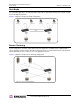
EMULEX MODEL 375 SAN STORAGE SWITCH USER ’S GUIDE CHAPTER 1: INTRODUCTION SWITCH APPLICATIONS The Emulex Model 375 SAN Storage Switch is ideal for consolidation and shared storage pooling, highperformance shared tape library backup and recovery, server clustering, and streaming rich media applications. The following sections provide examples of these applications.
EMULEX MODEL 375 SAN STORAGE SWITCH USER ’S GUIDE CHAPTER 1: INTRODUCTION Figure 1-2 depicts a sample multiple switch storage consolidation configuration in which multiple servers communicate with storage devices and zoning is incorporated. The zoning in Figure 1-2 might be set up to configure a multiple operating system environment. For example, Zone 1 might be Windows-based, Zone 2 might be Linux-based, and Zone 3 might be Unix-based.
EMULEX MODEL 375 SAN STORAGE SWITCH USER ’S GUIDE CHAPTER 1: INTRODUCTION Rich Media For rich media applications, the switch provides improved storage and file sharing from a single storage pool for multiple workstations. Figure 1-4 depicts a sample rich media configuration.
EMULEX MODEL 375 SAN STORAGE SWITCH USER ’S GUIDE CHAPTER 2 CHAPTER 2: SWITCH INSTALLATION SWITCH INSTALLATION Installation Preparation ................................................6 Switch Installation ........................................................7 Switch LEDs ................................................................9 SFP Compatibility ......................................................12 Booting the Switch and SAN ......................................
EMULEX MODEL 375 SAN STORAGE SWITCH USER ’S GUIDE CHAPTER 2: SWITCH INSTALLATION SWITCH INSTALLATION The switch can be installed in a rack or placed on a desktop. Rack Installation Installing the switch in an equipment rack requires an optional rack mount kit (sold separately). There are two kit variations currently available: • 24-inch Full Rack Mount Kit (Part Number 00651382), which supports equipment rack depths from 24 to 29.75 inches.
EMULEX MODEL 375 SAN STORAGE SWITCH USER ’S GUIDE CHAPTER 2: SWITCH INSTALLATION Installing the Retention Clips (optional) The switch ships with two, optional retention clips to secure the power cords in each power supply/fan module’s power receptacle. Screws (4) and washers (4) are provided for the clips. To install the retention clip: 1. Secure the retention clip to the switch by aligning the retention clip with the two screw holes located to the left and the right of the module’s power receptacle.
EMULEX MODEL 375 SAN STORAGE SWITCH USER ’S GUIDE CHAPTER 2: SWITCH INSTALLATION SWITCH LEDS The switch incorporates four sets of Light-Emitting Diodes (LEDs) to indicate ethernet, switch, port, and power supply/fan module status: 1. Ethernet LEDs – two separate LEDs indicating the network connection status. 2. System LEDs – four separate LEDs indicating the switch’s status. 3. Port LEDs – two LEDs per port indicating the port’s status. 4.
EMULEX MODEL 375 SAN STORAGE SWITCH USER ’S GUIDE CHAPTER 2: SWITCH INSTALLATION System LEDs The System LEDs indicate the switch’s status, independent of the port LEDs. Fault Power 2 Gb/s Switch Operational Figure 2-4: System LEDs System LEDs Indication Fault (yellow LED) • When lit, one or more of the ports has failed or the internal temperature has exceeded acceptable levels. • When flashing, all ports are operational but another error has occurred. Errors appear in an event log.
EMULEX MODEL 375 SAN STORAGE SWITCH USER ’S GUIDE CHAPTER 2: SWITCH INSTALLATION SFP Status LED (green LED) Port Bypassed LED (yellow LED) Flashing Off Activity. Data is being transferred between the port and device. On Off Normal operation but no activity. Port and device are fully operational. On Flashing Manually bypassed. A port can be manually bypassed using the Web Manager’s Bypass Port feature. On On Bypassed.
EMULEX MODEL 375 SAN STORAGE SWITCH USER ’S GUIDE CHAPTER 2: SWITCH INSTALLATION SFP COMPATIBILITY SFPs are “hot-pluggable” into the switch, which allows host computers, servers, and storage devices to be added dynamically without requiring power removal from the switch or any connected devices. The switch supports Small Form-Factor Pluggable (SFP) modules that comply with the SFP specification as produced by the MSA consortium and have passed Emulex’s qualification testing.
EMULEX MODEL 375 SAN STORAGE SWITCH USER ’S GUIDE BOOTING THE SWITCH CHAPTER 2: SWITCH INSTALLATION AND SAN The following procedure is recommended when booting the switch and SAN. Before powering on the switch and SAN, read the Release Notes, included with the switch contents, to determine any modifications that may be required for a specific installation. To boot the switch and SAN: 1. Power on the storage devices (such as JBODs, tape libraries, and RAIDs). 2.
EMULEX MODEL 375 SAN STORAGE SWITCH USER ’S GUIDE CHAPTER 2: SWITCH INSTALLATION POWER SUPPLY/FAN MODULE REPLACEMENT The Emulex® Model 375 SAN Storage Switch has hot-swappable power supply/fan modules for high availability. A power supply/fan module consists of an individual power supply and a fan bank consisting of three fans.
EMULEX MODEL 375 SAN STORAGE SWITCH USER ’S GUIDE CHAPTER 3 CHAPTER 3: SWITCH MANAGEMENT SWITCH MANAGEMENT Getting Started ...........................................................16 Managing the Switch..................................................21 Monitoring the Switch.................................................
EMULEX MODEL 375 SAN STORAGE SWITCH USER ’S GUIDE CHAPTER 3: SWITCH MANAGEMENT GETTING STARTED This section explains how to configure the switch’s ethernet network settings prior to using the Web Manager. Once the switch’s network settings are configured, use the Web Manager to perform a quick switch setup. Configuring the Network Interface Before using the Web Manager, ensure that the switch’s ethernet network parameter settings are correct for the network configuration.
EMULEX MODEL 375 SAN STORAGE SWITCH USER ’S GUIDE CHAPTER 3: SWITCH MANAGEMENT Connecting to the Web Manager The Web Manager displays current port utilization and health, enables easy to use Port Smart Settings and One-Step Zoning, and several additional features discussed later in this chapter. Note: The Web Manager supports Microsoft Internet Explorer for Windows version 5.5 or later and Internet Explorer for Apple version 5.2 or later. To connect to the Web Manager: 1.
EMULEX MODEL 375 SAN STORAGE SWITCH USER ’S GUIDE CHAPTER 3: SWITCH MANAGEMENT Command Button Description Cancel Cancels a request. This button is disabled until a configuration setting is changed or new information is entered. This button appears green to notify the user of a change to the switch configuration. Click this button to cancel the configuration change. Reboot Resets the switch. Login/Logout Logs in to and out of the switch. Refresh Redraws the currently displayed Web page.
EMULEX MODEL 375 SAN STORAGE SWITCH USER ’S GUIDE CHAPTER 3: SWITCH MANAGEMENT Initial Switch Setup Once a network connection has been established with the switch and an instance of the Web Manager is open, some basic switch configuration tasks are recommended: • Log in to the switch. • Change the switch’s password. • Verify the switch’s date and time settings. • Change the switch’s name.
EMULEX MODEL 375 SAN STORAGE SWITCH USER ’S GUIDE CHAPTER 3: SWITCH MANAGEMENT Step 3: Verify the Date and Time During the initial Web Manager session, the date and time for the switch are set based on the host system’s current settings. To view the current date and time: 1. Click Switch > Date & Time. The Switch Date & Time page appears. To set the date and time settings: 1. Enter the new date and time settings in the appropriate fields. 2. Click Submit.
EMULEX MODEL 375 SAN STORAGE SWITCH USER ’S GUIDE CHAPTER 3: SWITCH MANAGEMENT MANAGING THE SWITCH The Emulex® Model 375 SAN Storage Switch provides several options for managing and configuring the switch to meet the needs of the network environment. This section describes how to log in to the switch, configure switch and port settings, manage firmware and configuration files, and configure One-Step Zoning, Automatic Trunking, and Load Balancing.
EMULEX MODEL 375 SAN STORAGE SWITCH USER ’S GUIDE CHAPTER 3: SWITCH MANAGEMENT Logging in to the Switch The Web Manager requires users to log in to the switch when changes are made to the switch’s configuration. Log in is not required for viewing switch information. To log in to the switch: 1. Click Login on any Web Manager page. A message box appears confirming the login request. 2. Click OK. The Switch Login page appears. Figure 3-2: Switch Login page 3. Enter the switch’s password.
EMULEX MODEL 375 SAN STORAGE SWITCH USER ’S GUIDE CHAPTER 3: SWITCH MANAGEMENT General Switch Settings The Switch Configuration page displays general settings and switch identification information. To view the Switch Configuration page, click Switch > Configuration. Figure 3-3: Switch Configuration page Switch Identification This section includes general switch identification information. Setting Description Name The name of the switch. Location The location of the switch.
EMULEX MODEL 375 SAN STORAGE SWITCH USER ’S GUIDE CHAPTER 3: SWITCH MANAGEMENT To change the switch’s network location settings: 1. Click Switch > Configuration. 2. Enter the new value in the appropriate text box. 3. Click Submit. The Switch Configuration page displays the updated information. Version Information The different software and hardware versions include: Setting Description MAC ID A unique device address (MAC address) assigned to each switch at the factory.
EMULEX MODEL 375 SAN STORAGE SWITCH USER ’S GUIDE CHAPTER 3: SWITCH MANAGEMENT Setting SNMP Traps Simple Network Management Protocol (SNMP) uses traps to transmit information to SNMP-based network administration programs. The Switch SNMP Trap Configuration page displays information on the switch’s current SNMP trap configuration. To view the SNMP trap configuration page, click Switch > SNMP Traps. Figure 3-4: Switch SNMP Trap Configuration page To configure an SNMP trap: 1.
EMULEX MODEL 375 SAN STORAGE SWITCH USER ’S GUIDE CHAPTER 3: SWITCH MANAGEMENT Configuring Date and Time Settings The Switch Date & Time page displays the switch’s current date and time. During the initial Web Manager session, the date and time for the switch are set based on the host system’s current settings.
EMULEX MODEL 375 SAN STORAGE SWITCH USER ’S GUIDE CHAPTER 3: SWITCH MANAGEMENT Changing the Password The Switch Password page enables users to change the password for modifying the switch’s configuration. The same password is used to access both the Web Manager and the CLI. Note: Until the default switch password is changed, any user with knowledge of the default password can make changes to the switch’s configuration. To change the password: 1. Click Switch > Password. The Switch Password page appears.
EMULEX MODEL 375 SAN STORAGE SWITCH USER ’S GUIDE CHAPTER 3: SWITCH MANAGEMENT Adjusting the Switch Thresholds The Switch Thresholds page displays a variety of switch threshold settings. Setting Description Ordered Set Error Threshold The maximum number of OS errors allowed in a 10-second interval before a port is bypassed. Setting this value to "0" returns it to the factory default setting. This setting is activated on the Port Smart Settings page.
EMULEX MODEL 375 SAN STORAGE SWITCH USER ’S GUIDE CHAPTER 3: SWITCH MANAGEMENT Configuring the Port Smart Settings The Port Smart Settings page displays the current Smart Settings (configuration settings) assigned to each port and enables users to easily create and modify custom Smart Settings. To view the Port Smart Settings page: Click Port > Smart Settings. The Port Smart Settings page appears.
EMULEX MODEL 375 SAN STORAGE SWITCH USER ’S GUIDE CHAPTER 3: SWITCH MANAGEMENT Default Smart Settings There are several default Smart Settings available on the switch. These default Smart Settings were defined by Fibre Channel storage experts to ensure that the switch is optimally configured for performance and stability. The default Smart Settings cannot be modified or deleted, but these settings can be used as templates for creating custom Smart Settings.
EMULEX MODEL 375 SAN STORAGE SWITCH USER ’S GUIDE • CHAPTER 3: SWITCH MANAGEMENT When configuring multiple switches with a single cascade, use alternating ports. For example, connect the second switch using ports 1 and the third using ports 2 as shown in Figure 3-10. Figure 3-10: Alternating Ports for Single Cascades To assign a Smart Setting to one or more ports: 1. Select the appropriate Smart Setting from the list box. 2.
EMULEX MODEL 375 SAN STORAGE SWITCH USER ’S GUIDE CHAPTER 3: SWITCH MANAGEMENT To create a custom Smart Setting based on an existing Smart Setting: 1. Select a Smart Setting from the list box that most closely matches the port settings that the new Smart Setting should have. 2. Click Clone. 3. Enter the new Smart Setting name. A name may consist of up to 28 alphanumeric characters and cannot contain spaces (use underscores for spaces in names). 4. Click OK. The new Smart Setting is added to the list box.
EMULEX MODEL 375 SAN STORAGE SWITCH USER ’S GUIDE CHAPTER 3: SWITCH MANAGEMENT Port Information The following settings are available. Setting Description Smart Setting Name Displays the name of the Smart Setting. The Smart Setting name will automatically appear in the text box when selected in the scroll menu. Smart Setting Type The topology among switches for a port. Options include: • Initiator or Target Port – the default setting. Should be used when there are no links between switches.
EMULEX MODEL 375 SAN STORAGE SWITCH USER ’S GUIDE CHAPTER 3: SWITCH MANAGEMENT Change Notifications The following settings are available. Setting Description Stealth Intelligent Change Manager Stealth Intelligent Change Manager provides stability and control over change notification disruptions on a port basis. Options include: • Off: No Change Protection – no Stealth Intelligent Change Manager control.
EMULEX MODEL 375 SAN STORAGE SWITCH USER ’S GUIDE CHAPTER 3: SWITCH MANAGEMENT Port Recovery The following settings are available. Setting Description Bad Device Recovery When a port is already inserted into a zone, the port transforms F8 Failure notifications into F7 Initialization notifications. When this occurs, the port is bypassed and F7 Initialization notifications are allowed in the zone.
EMULEX MODEL 375 SAN STORAGE SWITCH USER ’S GUIDE CHAPTER 3: SWITCH MANAGEMENT Diagnostics The following settings are available. Setting Description Port Control The method for controlling a port. Options include: • auto – the default setting. The switch will automatically insert a port based on policy settings. This prevents the insertion of incompatible ports, which may cause disruption. • bypass – removes a port from the network.
EMULEX MODEL 375 SAN STORAGE SWITCH USER ’S GUIDE CHAPTER 3: SWITCH MANAGEMENT Managing Firmware and Configuration Files The Switch Files page displays information on the switch’s firmware and configuration files. To view the firmware and configuration files, click Switch > Files. The Switch Files page appears.
EMULEX MODEL 375 SAN STORAGE SWITCH USER ’S GUIDE CHAPTER 3: SWITCH MANAGEMENT To select the alternate firmware version for the next boot: 1. Under Next Boot Firmware Version, select Use Alternate Version on Next Reboot. The alternate firmware version currently displayed will be loaded on the next boot cycle. 2. Click Submit. 3. Click Reboot to reset the switch.
EMULEX MODEL 375 SAN STORAGE SWITCH USER ’S GUIDE CHAPTER 3: SWITCH MANAGEMENT One-Step Zoning Zoning allows ports to be divided into multiple virtual zones (or work groups), similar to Virtual Local Area Networking (VLAN). By separating activity on the network, zoning also eliminates change notification propagation (change notifications that occur within one zone cannot propagate to other zones.) Use zoning to: • Separate different operating system environments.
EMULEX MODEL 375 SAN STORAGE SWITCH USER ’S GUIDE CHAPTER 3: SWITCH MANAGEMENT The Zone Initialization Master Port field displays the port number of the port that is currently assigned as the master for that particular zone. The Initialization Master is responsible for starting the change notification process in each zone. To add ports to a zone: 1. Select the appropriate check boxes to place ports into zones. 2. Click Submit. To activate zoning: 1.
EMULEX MODEL 375 SAN STORAGE SWITCH USER ’S GUIDE CHAPTER 3: SWITCH MANAGEMENT Figure 3-14: Single switch zoning configuration Adding Devices to Multiple Zones In the previous example, each host only communicates with the devices in the same zone as the host. However, there may be situations in which hosts in separate zones need to share devices. When this situation occurs, use overlapping zones to share the devices between the hosts. Figure 3-15 depicts this type of zoning configuration.
EMULEX MODEL 375 SAN STORAGE SWITCH USER ’S GUIDE CHAPTER 3: SWITCH MANAGEMENT 3. Click Submit. Figure 3-16: Ports in Multiple Zones on the One-Step Zoning page Multiple Switch Zoning Zones can be configured across multiple switches using a similar procedure to a single switch. However, multiple-switch zoning requires some coordination between the switches. Note: To ensure zone integrity when configuring multiple switch zoning, you must implement AL_PA zoning through the Command Line Interface (CLI).
EMULEX MODEL 375 SAN STORAGE SWITCH USER ’S GUIDE CHAPTER 3: SWITCH MANAGEMENT To configure multiple-switch zoning, do the following for each switch: 1. Plan which ports should belong in each zone. 2. From the One-Step Zoning page, select the appropriate ports for each zone. Switch B Switch A Figure 3-18: Zones Coordinated on Multiple Switches 3. Ensure that the Zoning Active check box is selected for both switches.
EMULEX MODEL 375 SAN STORAGE SWITCH USER ’S GUIDE CHAPTER 3: SWITCH MANAGEMENT Connecting Ports Through Hard Zoning A Hard Zone can be used to add a separate 126 AL_PAs that operate in isolation from any other zone. A Hard Zone disables switching functionality and creates a shared connection between the ports in a zone topology, splitting the switch into multiple unique FC-AL zones. When Hard Zoning is enabled, all switch zones must be Hard Zones.
EMULEX MODEL 375 SAN STORAGE SWITCH USER ’S GUIDE CHAPTER 3: SWITCH MANAGEMENT Cascading Switches When multiple switches are connected, the connecting links between the switches are referred to as "cascades". There are two distinct cascade configurations to consider when configuring networks for optimal performance and connectivity: string cascades and tree cascades. String Cascades A string cascade connects multiple switches (up to three switches maximum) together in a "daisychained" configuration.
EMULEX MODEL 375 SAN STORAGE SWITCH USER ’S GUIDE CHAPTER 3: SWITCH MANAGEMENT Automatic Trunking Multiple links between switches are called “trunks”. Trunks provide higher bandwidth across cascaded switches for systems incorporating multiple initiators. Each trunk can improve system throughput and provide “failover” capability. A maximum of 4 trunks between each switch is supported. Trunking is performed automatically when ports are configured properly. Figure 3-22 is an example of Automatic Trunking.
EMULEX MODEL 375 SAN STORAGE SWITCH USER ’S GUIDE CHAPTER 3: SWITCH MANAGEMENT To assign ports to trunk groups: 1. Click Advanced Functions > Automatic Trunking. The Automatic Trunking page appears. Figure 3-23: Advanced Functions: Automatic Trunking page 2. Select a trunk group for each port by clicking the appropriate Trunk Group option. 3. When finished making changes, click Submit.
EMULEX MODEL 375 SAN STORAGE SWITCH USER ’S GUIDE CHAPTER 3: SWITCH MANAGEMENT In Figure 3-24, host 1 uses cascade port 1, while host 2 uses cascade port 2. All traffic will use the lowest numbered (primary) cascade port by default but ports may be configured to use other cascades.
EMULEX MODEL 375 SAN STORAGE SWITCH USER ’S GUIDE CHAPTER 3: SWITCH MANAGEMENT Fairness and Prioritization The concept of "fairness" is based on the principle of ensuring fair device access and communication across all devices in a storage system. The switch incorporates fairness and prioritization through InSpeed technology and Automatic Trunking and Load Balancing functionality.
EMULEX MODEL 375 SAN STORAGE SWITCH USER ’S GUIDE CHAPTER 3: SWITCH MANAGEMENT Switch Information Current status is provided for the following items. Item Status Indicators Switch Status • OK (green)–the switch unit is operating normally. • Fault (red)–one or more of the ports has failed, the internal temperature has exceeded acceptable levels, or another error has occurred. Errors appear in the event log.
EMULEX MODEL 375 SAN STORAGE SWITCH USER ’S GUIDE CHAPTER 3: SWITCH MANAGEMENT Port Utilization and Health Port utilization measures the amount of traffic passing into a port over a period of time. For example, if an initiator is transmitting data to a target, the initiator port displays a port utilization value (%) while the target port does not. If the same initiator is receiving data from the target, the target port displays a port utilization value (%) while the initiator port displays does not.
EMULEX MODEL 375 SAN STORAGE SWITCH USER ’S GUIDE CHAPTER 3: SWITCH MANAGEMENT Viewing the Event Log The Event Log contains a list of up to 3000 event log messages generated by the switch. The Switch Event Log page displays the event log messages with each message containing the following information: • Event Number – the number assigned to that specific event in the log. • Event Date and Time – the date and time when the event was recorded in the log.
EMULEX MODEL 375 SAN STORAGE SWITCH USER ’S GUIDE CHAPTER 3: SWITCH MANAGEMENT Viewing Port Information The Port Information page displays the Smart Settings, Serial ID (SID), and AL_PAs currently assigned to each port. Initiator AL_PAs are highlighted in blue to differentiate them from target AL_PAs. Note: The Initiator AL_PA information can be used to easily identify attached devices when configuring load balancing. To view port information: Click Port > Information. The Port Information page appears.
EMULEX MODEL 375 SAN STORAGE SWITCH USER ’S GUIDE CHAPTER 3: SWITCH MANAGEMENT Viewing Port Utilization Port utilization measures the amount of traffic passing through a port over a period of time. For example, if an initiator is transmitting data to a target, the initiator port displays a port utilization value (%) while the target port does not. If the same initiator is receiving data from the target, the target port displays a port utilization value (%) while the initiator port displays does not.
EMULEX MODEL 375 SAN STORAGE SWITCH USER ’S GUIDE CHAPTER 3: SWITCH MANAGEMENT Viewing Port Diagnostics This page displays diagnostic information pertaining to each port in the switch. Use the information provided on this page to diagnose abnormally high error counts on a particular port. To view the current diagnostic settings: Click Advanced Functions > Diagnostics > Port. The Port Diagnostics page appears.
EMULEX MODEL 375 SAN STORAGE SWITCH USER ’S GUIDE CHAPTER 3: SWITCH MANAGEMENT Statistic Description Bypass Port A single instance operation that forces a port into bypass mode. This feature may be used to diagnose device problems when a device is locked up or experiencing a high number of failures on a port. Reset Port A single instance operation that places a port in bypass mode and then immediately sets the port to auto-detect to re-insert the port.
EMULEX MODEL 375 SAN STORAGE SWITCH USER ’S GUIDE CHAPTER 3: SWITCH MANAGEMENT Viewing Ordered Sets This page displays the Ordered Sets that are being transmitted on the switch for each port since the last time the page was displayed. Ordered Sets are used when communicating data across networks to indicate actions, events, or status regarding the data. A list of detected Ordered Sets and their indications is provided below. To view ordered sets: 1. Click Advanced Functions > Diagnostics > Ordered Sets.
EMULEX MODEL 375 SAN STORAGE SWITCH USER ’S GUIDE CHAPTER 3: SWITCH MANAGEMENT Detection Indication F7 Initialization A port is in the non-participating mode and is attempting to win arbitration and begin initialization, possibly because the port was reset or is powering up. Sometimes the port is sending this sequence to another hot-cascaded switch, like a new initiator being inserted in the network. Change Notification A change notification has been detected and action has been taken.
EMULEX MODEL 375 SAN STORAGE SWITCH USER ’S GUIDE CHAPTER 4 CHAPTER 4: TECHNICAL REFERENCE TECHNICAL REFERENCE Troubleshooting Device Connections.........................59 Troubleshooting Management Connections ...............60 Port Bypass Conditions and Recovery .......................60 Default Smart Setting Attributes.................................61 Fibre Channel References .........................................
EMULEX MODEL 375 SAN STORAGE SWITCH USER ’S GUIDE CHAPTER 4: TECHNICAL REFERENCE TROUBLESHOOTING MANAGEMENT CONNECTIONS Problem Recommended Action Serial cable installed 1. Cycle power by reinstalling the power cord. but connection does 2. Check the terminal emulation program’s serial port parameters. not appear on terminal 3. Replace the serial cable. (Make sure it is a null modem cable.) Ethernet cable installed but Web Manager does not appear 1.
EMULEX MODEL 375 SAN STORAGE SWITCH USER ’S GUIDE CHAPTER 4: TECHNICAL REFERENCE Tree Cascade String Cascade --Trunk 1 String Cascade --Trunk 2 String Cascade --Trunk 3 String Cascade --Trunk 4 Initiator with Stealth Target with Stealth Fabric Connection Tree Cascade String Cascade --Trunk 1 String Cascade --Trunk 2 String Cascade --Trunk 3 String Cascade-Trunk 4 Smart Setting Type Initiator or Target Port Initiator or Target Port Initiator or Target Port Tree Cascade Tree Cascade Strin
EMULEX MODEL 375 SAN STORAGE SWITCH USER ’S GUIDE CHAPTER 4: TECHNICAL REFERENCE FIBRE CHANNEL REFERENCES The following books give useful information about Fibre Channel. • Alan F. Benner, Fibre Channel. McGraw-Hill, 1996. ISBN 0-07-005669-2. • Tom Clark, Designing Storage Area Networks. Addison Wesley Longman, 1999, ISBN 0-201-61584-3. • Jan Dedek, Fibre Channel - The Basics. ANCOT Corporation, 1997. ISBN 0-9637439-3-7. • Robert Kembel, Arbitrated Loop. Connectivity Solutions, 1996.
EMULEX MODEL 375 SAN STORAGE SWITCH USER ’S GUIDE APPENDIXES Appendixes EMULEX CORPORATION PART NUMBER 00041392-002 REV.
EMULEX MODEL 375 SAN STORAGE SWITCH USER ’S GUIDE APPENDIX A APPENDIX A: SPECIFICATIONS Specifications SWITCH SPECIFICATIONS Specification Value Number of Ports 20 Operating Rate All ports operate at 1.0625 or 2.125 Gbps (selectable) Port Media Type SFP Enclosure 1U full-rack form-factor Management Interface RS-232 or 10/100 Ethernet Operating Mode Switching or Non-switching modes Configurability Management interface configurable Power On Selftest (POST) Yes Dimensions 17.20" x 1.
EMULEX MODEL 375 SAN STORAGE SWITCH USER ’S GUIDE APPENDIX B APPENDIX B: CLI QUICK REFERENCE CLI Quick Reference Connecting to the CLI ................................................65 Logging In and Out ....................................................65 Using the CLI .............................................................66 Frequent Switch Configuration Tasks.........................66 CLI Commands ..........................................................
EMULEX MODEL 375 SAN STORAGE SWITCH USER ’S GUIDE USING THE APPENDIX B: CLI QUICK REFERENCE CLI The CLI enables users to monitor and change system and port configurations, configure One-Step Zoning, Automatic Trunking, Load Balancing, and event reporting parameters, and download and install firmware. For additional information on the CLI, see the Emulex® or InSpeed™ Storage Switch Products’ CLI Reference Guide. To enter a command: Type the command text or the number of the command.
EMULEX MODEL 375 SAN STORAGE SWITCH USER ’S GUIDE APPENDIX B: CLI QUICK REFERENCE CLI COMMANDS All of the CLI commands for the Emulex® Model 375 SAN Storage Switch are shown below in a tree diagram. Using the “help” command at the command line may provide additional information. root --> 1. config --> help li lo save 1. save 2. sys --> 1. speed 2. mode 3. oserr 4. crcerr 5. blkarb 6. clkd 7. time 8. lipen 9. name 10. location 11. contact 12. syslog 13. events 14. sev 15. fault 16. evclr 17.
EMULEX MODEL 375 SAN STORAGE SWITCH USER ’S GUIDE APPENDIX C APPENDIX C: EVENT MESSAGES Event Messages The event messages for the switch are listed below. For explanations, contact a customer service representative. The message’s applicable severity level as defined below is also provided.
EMULEX MODEL 375 SAN STORAGE SWITCH USER ’S GUIDE APPENDIX C: EVENT MESSAGES Event Event Message Severity 82 PORT is ready to be inserted DBG 83 Segment stall on PORT # NOTIFY 84 Bad Open on PORT # WRN 85 Error during Port Disc.
EMULEX MODEL 375 SAN STORAGE SWITCH USER ’S GUIDE APPENDIX D APPENDIX D: AL_PA CROSS REFERENCES AL_PA Cross References Arbitrated Loop Physical Addresses AL_PA AL_PA ID AL_PA AL_PA ID AL_PA AL_PA ID (hex) (hex) (decimal) (hex) (hex) (decimal) (hex) (hex) (decimal) EF E8 E4 E2 E1 E0 DC DA D9 D6 D5 D4 D3 D2 D1 CE CD CC CB CA C9 C7 C6 C5 C3 BC BA B9 B6 B5 B4 B3 B2 B1 AE AD AC AB AA A9 A7 A6 A5 00 01 02 03 04 05 06 07 08 09 0A 0B 0C 0D 0E 0F 10 11 12 13 14 15 16 17 18 19 1A 1B 1C 1D 1E 1F 20
EMULEX MODEL 375 SAN STORAGE SWITCH USER ’S GUIDE APPENDIX E APPENDIX E: GLOSSARY Glossary AL_PA or Arbitrated Loop Physical Address A one-byte value used to identify a port in an Arbitrated Loop topology. The value of the AL_PA corresponds to bits 7:0 of the 24-bit Native Address Identifier. Arbitration The process of selecting one respondent from a group requesting service at the same time. Close (CLS) An Arbitrated Loop protocol used to terminate a loop circuit.
EMULEX MODEL 375 SAN STORAGE SWITCH USER ’S GUIDE INDEX Index A E AL_PA Cross References 70 AL_PA zoning 43 ethernet LEDs 9 event log 52 messages 68 B Bad Device Recovery policy 35 Bad Zone Recovery policy 43 Blocking ARB 24 Bypass on Clock Delta policy 36 Bypass on CRC Error policy 35 Bypass on No Activity policy 35 Bypass on OS Error policy 35 F C G cascades 45 strings 45 trees 45 Change Notification on Insertion policy 34 Change Notification on Removal policy 34 change notifications 34 Clear on
EMULEX MODEL 375 SAN STORAGE SWITCH USER ’S GUIDE INDEX M LED 11 powering on the switch 13 pre-insertion testing 33 prioritization of devices 49 managing the switch 21 monitoring the switch 49 N R network interface configuration 16 network settings 23 rack installation 7 UL guidelines 7 references, Fibre Channel 62 O operating conditions 64 operating speed 24 ordered sets 57 overview 1 S P password 65 changing 27 policies 33, 34, 35, 36 Bad Device Recovery 35 Bypass on Clock Delta 36 Bypass on CR
EMULEX MODEL 375 SAN STORAGE SWITCH USER ’S GUIDE LEDs 9 load balancing 47 management 15, 21 monitoring 49 network settings 23 operating conditions 64 ordered sets 57 overview 1 package contents 6 policies 33, 34, 35, 36 port diagnostics 55 port information 53 port utilization 54 powering on 13 settings 22 specifications 64 speed 24 status 49 telnet session 27 thresholds 28 trunking 46 unpacking 6 version 24 Web Manager login 22 zoning 39, 40, 41, 42 system LEDs 10 T Target with Stealth Smart Setting 30 t