eBOX832-840 Series Embedded System User’s Manual
Disclaimers This manual has been carefully checked and believed to contain accurate information. AXIOMTEK Co., Ltd. assumes no responsibility for any infringements of patents or any third party’s rights, and any liability arising from such use. AXIOMTEK does not warrant or assume any legal liability or responsibility for the accuracy, completeness or usefulness of any information in this document. AXIOMTEK does not make any commitment to update the information in this manual.
Safety Precautions Before getting started, please read the following important safety precautions. 1. 2. 3. 4. The eBOX832-840 Series does not come equipped with an operating system. An operating system must be loaded first before installing any software into the computer. Be sure to ground yourself to prevent static charge when installing the internal components. Use a grounding wrist strap and place all electronic components in any staticshielded devices.
Classification 1. 2. 3. 4. 5. Degree of production against electric shock: not classified Degree of protection against the ingress of water: IPX0 Equipment not suitable for use in the presence of a flammable anesthetic mixture with air or with oxygen or nitrous oxide. Mode of operation: Continuous Type of protection against electric shock: Class I equipment General Cleaning Tips You may need the following precautions before you begin to clean the computer.
z z z z a component. Although paper towels or tissues can be used on most hardware as well, we still recommend you to rub it with a piece of cloth. Water or rubbing alcohol: You may moisten a piece of cloth a bit with some water or rubbing alcohol and rub it on the computer. Unknown solvents may be harmful to the plastics parts. Vacuum cleaner: Absorb the dust, dirt, hair, cigarette particles, and other particles out of a computer can be one of the best methods of cleaning a computer.
Scrap Computer Recycling If the computer equipments need the maintenance or are beyond repair, we strongly recommended that you should inform us as soon as possible for the suitable solution. For the computers that are no longer useful or no longer work well, please contact us for recycling and we will make the proper arrangement. Trademarks Acknowledgments AXIOMTEK is a trademark of AXIOMTEK Co., Ltd. IBM, PC/AT, PS/2, VGA are trademarks of International Business Machines Corporation.
Table of Contents Disclaimers ........................................................................................................... ii Safety Precautions .............................................................................................. iii Classification ........................................................................................................iv General Cleaning Tips .........................................................................................
MEMO viii
eBOX832-840 Series User’s Manual Chapter 1 Introduction This chapter contains general information and detailed specifications of the eBOX832-840 Series. Chapter 1 includes the following sections: 1.1 General Description System Specification Dimensions I/O Outlets Package List General Description The eBOX832-840 Series is an embedded system that can support ® TM Socket P (478-pin) for Intel Core ® 2 Duo/ Celeron M processor.
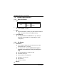
eBOX832-840 Series User’s Manual 1.2 System Specifications 1.2.1 Main CPU Board CPU z Model eBOX832-840 series Socket Socket P (478-pin) CPU Intel ® TM Core 2 Duo/ Celeron ® M z System Chipset ® Intel 965GME + ICH8M BIOS z Phoenix-Award BIOS, 16Mbit (SPI) with RPL/PXE LAN Boot ROM, SmartView and Customer CMOS Backup. System Memory z 1.2.2 Two 240-pin DDR2-533/667DIMM max. up to 4GB (The actual max. capacity will be less depending on system configuration.
eBOX832-840 Series User’s Manual Dual Gigabit Ethernet; 1st via intel 82566DM and 2nd via Intel 82573V Introduction 3
eBOX832-840 Series User’s Manual 1.2.3 System Specification Disk Drive z Supports one 2.5” SATA HDD Power Supply z 250W AC-DC Power Input z 100~240VAC, 50/60Hz, Max. 10A Dimensions z 300mm(W) x 104.5mm(H) x 210mm (D) Operation Temperature z 0℃-45℃; Relative Humidity: 10%-95% NOTE All specifications and images are subject to change without notice.
eBOX832-840 Series User’s Manual 1.3 Dimensions 300.00 1 The following diagrams show you dimensions and outlines of the eBOX832-840 Series. 4 3 2 104.50 210.00 130.00 285.
eBOX832-840 Series User’s Manual 1.4 I/O Outlets The following figures show you I/O outlets on front and rear panels of the eBOX832-840 Series. Front Panel z p o No. Connector n Power & HDD LED o USB p Optical Drive Rear Panel z u t s o No. n o p q 6 n Connector PCIe x16 Slot COM2~4 Mic-In & Line-Out 1394a & USB r q p n No.
eBOX832-840 Series User’s Manual 1.5 Packing List The package bundled with your eBOX832-840 Series should contain the following items: z z z z z z eBOX832-840 Series Unit x 1 Power Cord x 1 CD x 1 (For Driver and User’s Manual) Quick Manual x 1 M3-12.5 Screws x 4 M3-6 Screws x 4 If you can not find this package or any items are missing, please contact AXIOMTEK distributors immediately.
eBOX832-840 Series User’s Manual Chapter 2 Hardware Installation The eBOX832-840 Series are convenient for your various hardware configurations, such as CPU (Central Processing Unit), HDD (Hard Disk Drive). The chapter 2 will show you how to install the hardware. It includes: 2.1 Installing the Processor ® The eBOX832-840 Series supports Socket P (478-pin) for Intel ® CoreTM 2 Duo/ Celeron M CPUs. Please carefully follow up these steps below to install the CPU: Step 1 Turn off the system.
eBOX832-840 Series User’s Manual Step 4 Remove the cover from the chassis. Step 5 Before installing your CPU, please check and confirm all jumpers are correctly set. Locate the socket on the board.
eBOX832-840 Series User’s Manual Step 6 Align pins of the CPU with pin holes of the socket. Be careful of the CPU’s orientation that you need to align the arrow mark on the CPU with the arrow key on the socket. Place the CPU into the socket, and use a screwdriver to lock it onto the socket. Step 7 If users frequently assemble and disassemble the heat sink, the tin plate in the middle might be damaged.
eBOX832-840 Series User’s Manual Step 8 The damaged tin plate is likely to make a problem of thermal dissipation to cause a system shutdown. Therefore, users might need to apply a layer of heat sink paste between the CPU and the tin plate of heat sink for better thermal dissipation. Step 9 Place the heat sink on the CPU, and use a screwdriver to lock it down.
eBOX832-840 Series User’s Manual Step 10 Close the cover to the chassis, and fasten all screws.
eBOX832-840 Series User’s Manual 2.2 Installing the Memory Module Step 1 Turn off the system. Step 2 Unplug the AC power-cord. Step 3 Loosen seven screws marked as the illustration below to open side covers.
eBOX832-840 Series User’s Manual Step 4 Remove the top cover from the chassis. Step 5 Install the Memory Module.
eBOX832-840 Series User’s Manual Step 6 Put back the top cover to the chassis, and fasten seven screws marked as the illustration below to close side covers.
eBOX832-840 Series User’s Manual 2.3 Installing the Hard Disk Drive The eBOX832-840 Series offers a convenient drive bay module for users to install HDD. The system offers users one 2.5” Hard Disk Drive for installation. Please follow the steps: Step 1 Turn off the system. Step 2 Unplug the AC power-cord. Step 3 Loosen ten screws marked as the illustration below to open the back cover.
eBOX832-840 Series User’s Manual Step 4 Remove the back cover from the chassis. Step 5 These are HDD assembly parts: - HDD Bracket x 1 - 2.
eBOX832-840 Series User’s Manual Step 6 Use these assembly parts to fix HDD with the bracket. Step 7 Install the HDD inside the system. Step 8 Plug the SATA and Power cables in HDD. Step 9 Close the back cover to the chassis, and fasten all screws.
eBOX832-840 Series User’s Manual 2.4 Installing the PCI Card Step 1 Turn off the system. Step 2 Unplug the AC power-cord. Step 3 Loosen ten screws marked as the illustration below to open the back cover.
eBOX832-840 Series User’s Manual Step 4 Align the PCIe x16 for discrete graphic card or ADD2+ card with the slot on the left side, and the bracket with the slot on the rear panel. Step 5 Press the PCIe x16 for discrete graphic card or ADD2+ card into the slot on the left side, and latch the bracket with the slot on the rear panel.
eBOX832-840 Series User’s Manual Step 6 Once the card is seated in the slot, screw the bracket onto the rear panel. Step 7 Close the back cover to the chassis and fasten all screws.
eBOX832-840 Series User’s Manual Chapter 3 Award BIOS Utility The Phoenix-Award BIOS provides users with a built-in Setup program to modify basic system configuration. All configured parameters are stored in a battery-backed-up RAM (CMOS RAM) to save the Setup information whenever the power is turned off. 3.1 Entering Setup There are two ways to enter the Setup program.
eBOX832-840 Series User’s Manual 3.
eBOX832-840 Series User’s Manual 3.4 The Main Menu Once you enter the Award BIOS CMOS Setup Utility, the Main Menu appears on the screen. In the Main Menu, there are several Setup functions and a couple of Exit options for your selection. Use arrow keys to select the Setup Page you intend to configure then press to accept or enter its sub-menu.
eBOX832-840 Series User’s Manual 3.5 Standard CMOS Setup Menu The Standard CMOS Setup Menu displays basic information about your system. Use arrow keys to highlight each item, and use or key to select the value you want in each item. z Date The date format is , . Press to show the calendar. day date month year z It is determined by the BIOS and read only, from Sunday to Saturday. It can be keyed with the numerical/ function key, from 1 to 31.
eBOX832-840 Series User’s Manual military-time clock. For example, 1 p.m. is 13:00:00. z IDE Channel Master/IDE Channel Slave These items identify the types of each IDE channel installed in the computer. There are 45 predefined types (Type 1 to Type 45) and 2 user’s definable types (Type User) for Enhanced IDE BIOS. Press /<+> or /<−> to select a numbered hard disk type, or directly type the number and press . Please be noted your drive’s specifications must match the drive table.
eBOX832-840 Series User’s Manual z Halt On This item determines whether the system will halt or not, if an error is detected while powering up. No errors All errors The system booting will halt on any errors detected. (default) Whenever BIOS detects a non-fatal error, the system will stop and you will be prompted. All, But Keyboard The system booting will not stop for a keyboard error; it will stop for other errors.
eBOX832-840 Series User’s Manual 3.6 Advanced BIOS Features This section allows you to configure and improve your system, to set up some system features according to your preference.
eBOX832-840 Series User’s Manual z CPU Feature Scroll to this item and press to view the CPU Feature sub menu. z Hard Disk Boot Priority Scroll to this item and press to view the sub menu to decide the disk boot priority.
eBOX832-840 Series User’s Manual Press to return to the Advanced BIOS Features page. z CPU L1 & L2 Cache These two options speed up memory access. However, it depends on the CPU/chipset design. The default setting is “Enabled”. CPUs without built-in internal cache will not provide the “CPU Internal Cache” item on the menu.
eBOX832-840 Series User’s Manual Enabled Disabled z z Boot Up NumLock Status Set the the Num Lock status when the system is powered on. The default value is “On”. Gate A20 Option The default value is “Fast”. Normal Fast z The A20 signal is controlled by keyboard controller or chipset hardware. Default: Fast. The A20 signal is controlled by Port 92 or chipset specific method. Typematic Rate Setting This item determines the typematic rate of the keyboard. The default value is “Disabled”.
eBOX832-840 Series User’s Manual held-down key begins generating repeat characters. The default value is “250”. 250 500 750 1000 z 250 msec 500 msec 750 msec 1000 msec Security Option This item allows you to limit access to the system and Setup, or just to Setup. The default value is “Setup”. System Setup If a wrong password is entered at the prompt, the system will not boot, the access to Setup will be denied, either.
eBOX832-840 Series User’s Manual 3.7 Advanced Chipset Features Since the features in this section are related to the chipset on the CPU board and are completely optimized, you are not recommended to change the default settings in this setup table unless you are well oriented with the chipset features. z DRAM Timing By SPD Use this item to enable or disable the SDRAM timing, which can be defined by Serial Presence Detect. z CAS Latency Time You can select CAS latency time to HCLKs 2, 3, or Auto.
eBOX832-840 Series User’s Manual CAS and RAS strobe signals, used when DRAM is written to, read from, or refreshed. z DRAM RAS# Precharge The precharge time is the number of cycles it takes for the RAS to accumulate its charge before DRAM refresh. If insufficient time is allowed, refresh may be incomplete and the DRAM may fail to retain data. z Precharge Delay The precharge time is the number of cycles it takes for DRAM to accumulate its charge before refresh.
eBOX832-840 Series User’s Manual z PCI Express Root Port Func Scroll to this item and press to view the sub menu to decide the PCI Express Port. Press to return to the Advanced Chipset Featurs page, and press it again, return to the Main Menu page. *** VGA Setting *** z z z PEG/Onchip VGA Control This setting allows you to select whether to use the onchip graphics processor or the PCI Express card.
eBOX832-840 Series User’s Manual z z z z Use this item to set the VGA frame buffer size. DVMT Mode DVMT (Dynamic Video Memory Technology) helps you select the video mode. DVMT/Fixed Memory Size DVMT (Dynamic Video Memory Technology) allows you to select a maximum size of dynamic amount usage of the video memory. The system would configure the video memory dependent on your application. Boot Display This item is to select Display Device that the screen will be shown.
eBOX832-840 Series User’s Manual z OnChip IDE Device Scroll to this item and press to view the sub menu OnChip IDE Device. ¾ ¾ ¾ IDE HDD Block Mode Block mode is also called block transfer, multiple commands, or multiple sector read/write. If your IDE hard drive supports block mode (most new drives do), select Enabled for automatic detection of the optimal number of block read/writes per sector the drive can support.
eBOX832-840 Series User’s Manual ¾ ¾ Slave PIO and/or IDE Secondary Master/Slave PIO items on the menu. IDE Primary/Secondary Master/Slave PIO The four IDE PIO (Programmed Input/Output) fields let you set a PIO mode (0-4) for each of the four IDE devices that the onboard IDE interface supports. Modes 0 to 4 provide successively increased performance. In Auto mode, the system automatically determines the best mode for each device.
eBOX832-840 Series User’s Manual z Onboard Device Scroll to this item and press to view the sub menu Onboard Device. ¾ ¾ ¾ ¾ USB Controller Enable this item if you are using the USB in the system. You should disable this item if a higher-level controller is added. USB 2.0 Controller Enable this item if you are using the EHCI (USB2.0) controller in the system. USB Keyboard Support Enable this item if the system has a Universal Serial Bus (USB) controller, and you have a USB keyboard.
eBOX832-840 Series User’s Manual z Super IO Device Scroll to this item and press to view the sub menu Super IO Device. ¾ ¾ ¾ ¾ ¾ 40 Onboard FDC Controller Select Enabled, if your system has a floppy disk controller (FDC) installed on the system board and you want to use it. If you install and-in FDC or the system has no floppy drive, select Disabled in this field. Options: “Enabled” and “Disabled”. Onboard Serial Port 1/2 Select an address and corresponding interrupt for the serial port.
eBOX832-840 Series User’s Manual ¾ ¾ ¾ ¾ ¾ ¾ Serial Port 4 Use IRQ This item selects a corresponding interrupt for the fourth serial port. Onboard Paralellel Port This item allows you to determine the I/O address for onboard parallel port. Options are: “378H/IRQ7”, “278H/IRQ5”, “3BC/IRQ7” and “Disabled”. Parallel Port Mode Select an operating mode for the onboard parallel (printer) port. Select Normal unless your hardware and software require another mode in this field.
eBOX832-840 Series User’s Manual 3.9 Power Management Setup The Power Management Setup allows you to save energy of your system effectively. It will shut down the hard disk and turn OFF video display after a period of inactivity.
eBOX832-840 Series User’s Manual z PCI Express PM Func Scroll to this item and press to view the sub menu PCI Express PM Function. Press to return to the Advanced Chipset Featurs page. z ACPI Function This item allows you to enable/disable the Advanced Configuration and Power Management (ACPI). The function is always defaulted in the “Enabled” mode. z ACPI Suspend Type This item specifies the power saving modes for ACPI function.
eBOX832-840 Series User’s Manual save energy. The information stored in memory will be used to restore the system when a “wake up” event occurs. z Power Management This option allows you to select the type (or degree) of power saving for Doze, Standby, and Suspend modes. The table below describes each power management mode: Max Saving User Define Min Saving Disabled z It is maximum power savings, only available for SL CPUs. The inactivity period is 1 minute in each mode. It sets each mode.
eBOX832-840 Series User’s Manual all devices except the CPU shut off. The default value is “Disabled”. Disabled 1/2/4/6/8/10/2 0/30/40 Min/1 Hr System will never enter SUSPEND mode Defines the continuous idle time before the system entering SUSPEND mode.
eBOX832-840 Series User’s Manual z Primary/Secondary IDE 0/1 Use this item to configure the IDE devices monitored by the system. z FDD, COM, LPT Port Use this item to configure the FDD, COM and LPT ports monitored by the system. z PCI PIRQ[A-D]# This item can be used to detect PCI device activities; if no activity, the system will enter the sleep mode. Press to return to the Main Menu page. 3.10 PnP/PCI Configuration Setup This section describes configuring the PCI bus system.
eBOX832-840 Series User’s Manual z Reset Configuration Data Normally, you leave this item Disabled. Select Enabled to reset Extended System Configuration Data (ESCD) when you exit Setup or if installing a new add-on cause the system reconfiguration a serious conflict that the operating system can not boot. Options: Enabled, Disabled. z Resources Controlled By The Award Plug and Play BIOS can automatically configure all boot and Plug and Play-compatible devices.
eBOX832-840 Series User’s Manual 48 Award BIOS Utility
eBOX832-840 Series User’s Manual 3.11 PC Health Status This section supports hardware monitering that lets you monitor those parameters for critical voltages, temperatures and fan speed of the board. z CPU Temperature The current system CPU temperature will be automatically detected by the system. z SYSTEM Temperature Show you the current system1 temperature. z FAN1 Speed Show you the current system fan1 temperature. z FAN2 Speed Show you the current system fan2 temperature. z Vcore +3.
eBOX832-840 Series User’s Manual 3.12 Frequency/Voltage Control This section is to control the CPU frequency and Supply Voltage, DIMM OverVoltage and AGP voltage. z Auto Detect PCI Clk The item enables or disables the auto detection of the PCI clock. z Spread Spectrum This item is to adjust extreme values of the pulse for EMI test. Press to return to the Main Menu page.
eBOX832-840 Series User’s Manual 3.13 Load Optimized Defaults This option allows you to load the default values to your system configuration. These default settings are optimal and enable all high performance features. To load SETUP defaults value to CMOS SRAM, enter “Y”. If not, enter “N”.
eBOX832-840 Series User’s Manual 3.14 Set Supervisor/User Password You can set either supervisor or user password, or both of then. The differences between are: 1. 2. Supervisor password: can enter and change the options of the setup menus. User password: just can enter but do not have the right to change the options of the setup menus. When you select this function, the following message will appear at the center of the screen to assist you in creating a password.
eBOX832-840 Series User’s Manual 3.15 Save & Exit Setup This allows you to determine whether or not to accept the modifications. Typing “Y” quits the setup utility and saves all changes into the CMOS memory. Typing “N” brigs you back to Setup utility.
eBOX832-840 Series User’s Manual 3.16 Exit Without Saving Select this option to exit the Setup utility without saving the changes you have made in this session. Typing “Y” will quit the Setup utility without saving the modifications. Typing “N” will return you to Setup utility.