
Datasheet


Hardware specification SP1ML
8/27 DocID026906 Rev 3
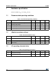
1.6 Pin assignment
Table 6. Pin assignment
Pin Name Type Description STM32L pin
(1)
1 TXRXLED O Active low Tx/Rx LED drive
(2)
PA2
2 SHDN I Shutdown PA0
3 GPIO0 I/O General purpose input/output 0
(3)
PB15
4 GPIO1 I/O General purpose input/output 1
(3)
PB14
5 MODE0 I Protocol mode selection 0
(2)
PB13
6 MODE1 I Protocol mode selection 1
(2)
PB12
7 VDD Power Supply input voltage -
8 GND Power Ground -
9 SWDIO I/O Serial wire I/O PA13
10 SWCLK I Serial wire clock PA14
11 BOOTMODE I Boot mode selection BOOT0
12 RESET I Reset input, active low NRST
13 TXD O UART transmit data PA9
14 RXD I UART receive data PA10
15 GPIO2 I/O General input/output 2
(3)
PB6
16 GPIO3 I/O General purpose input/output 3
(3)
PB7
1. For further details, see the STM32L151RB datasheet, Pin descriptions section. Alternate functions of any given pin are
dependent on the user application firmware that is loaded into the module and is beyond the scope of this document.
2. Refer to Hardware design section for details regarding TXRXLED and protocol mode selection.
3. The GPIO signals are not used by the default firmware integrated in the module. They are accessible with user application
firmware. See note 1.