Z8ENCORE000ZCO Z8 Encore!® Flash Microcontroller Development Kit User Manual UM014605-0208 Copyright ©2008 by Zilog®, Inc. All rights reserved. www.zilog.
Z8 Encore!® Flash Microcontroller Development Kit User Manual ii Revision History Each instance in Revision History reflects a change to this document from its previous revision. For more details, refer to the corresponding pages and appropriate links in the table below. Date Revision Level Description Page No February 2008 05 Updated Zilog logo, changed ZiLOG to Zilog, implemented style guide and template. Deleted ’Figure 7-Figure to be added at a later revision’ in Smart Cable section.
Z8 Encore!® Flash Microcontroller Development Kit User Manual iii Table of Contents Introduction . . . . . . . . . . . . . . . . . . . . . . . . . . . . . . . . . . . . . . . . . . . . 1 Kit Contents . . . . . . . . . . . . . . . . . . . . . . . . . . . . . . . . . . . . . . . . . 1 Hardware . . . . . . . . . . . . . . . . . . . . . . . . . . . . . . . . . . . . . . . . 1 Software (on CD-ROM) . . . . . . . . . . . . . . . . . . . . . . . . . . . . . 2 Documentation . . . . . . . . . . . . . . . . . . . . .
Z8 Encore!® Flash Microcontroller Development Kit User Manual iv Pushbuttons . . . . . . . . . . . . . . . . . . . . . . . . . . . . . . . . . . . . . . . . Schematics . . . . . . . . . . . . . . . . . . . . . . . . . . . . . . . . . . . . . . . . . . . Index. . . . . . . . . . . . . . . . . . . . . . . . . . . . . . . . . . . . . . . . . . . . . . . . . Customer Support. . . . . . . . . . . . . . . . . . . . . . . . . . . . . . . . . . . . . .
Z8 Encore!® Flash Microcontroller Development Kit User Manual 1 Introduction Zilog’s Z8 Encore!® Flash Microcontroller (MCU) is the first in the new line of Zilog microcontroller products. This board supports the Z8 Encore! and introduces Flash to the Z8® line of microcontrollers. The Z8 Encore! Development Kit (Z8ENCORE000ZCO) allows you to become familiar with the hardware and software tools available with this product.
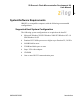
Z8 Encore!® Flash Microcontroller Development Kit User Manual 2 Z Smart Cable Registration Card Quick Start Guide Evaluation Board 9 V DC Universal Power Supply Software Documentation CD Figure 1.
Z8 Encore!® Flash Microcontroller Development Kit User Manual 3 Documentation The following documentation are included in the Z8 Encore! development kit: • • • Programmer’s Reference Sheet Registration card Z8 Encore!® technical documentation (on CD-ROM) – ZDS II—IDE User Manual – eZ8 CPU User Manual – Product Specification – Product briefs – Application notes – Programmer’s Reference Sheet – Flyers – Product Line Card The sample code is installed with ZDS II and is located in the
Z8 Encore!® Flash Microcontroller Development Kit User Manual 4 System/Software Requirements IBM PC (or compatible computer) with the following recommended configurations: Supported Host System Configuration The following system configurations are required on the host PC: • Microsoft Windows XP SP1/Windows 2000 SP3/Windows NT 4.0 SP6/Windows 98 SE • • • • • • Pentium II/233 MHz processor or higher up to Pentium IV, 2.
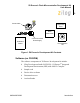
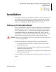
Z8 Encore!® Flash Microcontroller Development Kit User Manual 5 Installation This chapter describes the installation of hardware and software tools for the Z8 Encore! Evaluation Kit. Also describes setting up the evaluation board, substituting plug configurations of the universal 9 V DC power supply, and installing the ZDS II—IDE Z8 Encore! software. Setting up the Evaluation Board The PC communicates with the Z8 Encore! Flash MCU Evaluation board using the serial port of the PC.
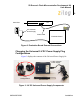
Z8 Encore!® Flash Microcontroller Development Kit User Manual 6 Serial Port Z PC 9 V Universal Power Supply Smart Cable Evaluation Board Figure 2. Evaluation Board External Connections Changing the Universal 9 V DC Power Supply Plug Configurations Figure 3 displays the contents of the Universal Power Supply kit. 9 V DC Universal Power Supply Plug Configurations Removal Tool Figure 3.
Z8 Encore!® Flash Microcontroller Development Kit User Manual 7 The 9 V DC universal power supply features three different plug configurations, the power supply and a tool that aids in removing one plug configuration to insert another. Follow the steps below to substitute one plug configuration for another: 1. Using the removal tool, place the power supply in the round hole at the top of the current plug configuration. 2.
Z8 Encore!® Flash Microcontroller Development Kit User Manual 8 Installing the ZDS II—Z8 Encore!® Software Follow the steps below to install the software tools: 1. Note: Load the ZDS II—Z8 Encore! Flash MCU CD into the CD-ROM drive of the host PC. The CD launches DemoShield automatically and provides a menu to install the product and documentation. Select INSTALL PRODUCTS followed by INSTALL ZDS II to display the Installation Wizard.
Z8 Encore!® Flash Microcontroller Development Kit User Manual 9 Getting Started Using ZDS II Follow the steps below to open an existing project: 1. Connect the Evaluation board to the host PC’s serial communications port using the Smart Cable. 2. Apply 9 V DC power to the Evaluation board. 3. Run the ZDS II Software (Start > Programs > ZDS II-Z8 Encore! F640x_ZDS II-28 Encore! F640x_). 4. Select Open Project from the File menu. The Open Project dialog box appears. 5.
Z8 Encore!® Flash Microcontroller Development Kit User Manual 10 Z8 Encore!® Evaluation Board Introduction Z8 Encore! evaluation board (64 KB version) is an evaluation and prototyping board for the Z8 Encore!® family of MCUs. The board provides you with a tool to evaluate features of Z8 Encore! family, and to develop an application before building the hardware.
Z8 Encore!® Flash Microcontroller Development Kit User Manual 11 Block Diagram The board consists of the following major blocks: • • • • • • • Z8 Encore!® MCU Serial communication devices (SPI and I2C) Power and communication interfaces LED array Expansion Module interfaces IrDA transceiver Zilog Debug Interface (DBG) 7 3 6 4 5 5 1 2 Figure 5.
Z8 Encore!® Flash Microcontroller Development Kit User Manual 12 Figure 6 displays the Z8 Encore!® evaluation board block diagram. Temp. Sensor ID SEL Port A[0:7] Port B[0:7] Port C[0:7] Port D[0:7] LED ARRAY Port E[0:7] Port F[0:7] Port G[0:7] RS485_1 RS-232 Modem Phone Line RS-485 Port F Port B RS-485 Port H Console Port G RS-232 Port E IrDA Port D IrDA Port C Z8 Encore!® MCU Port A Port H[0:3] Embedded Modem RS485_2 Expansion Module Interface Figure 6.
Z8 Encore!® Flash Microcontroller Development Kit User Manual 13 MCU The Z8 Encore! MCU family of products are the first in a line of Zilog MCU products based upon the new 8-bit eZ8 core CPU. The Flash in-circuit programming capability allows for faster development time and program changes in the field. The new eZ8 core CPU is upward compatible with existing Z8® instructions.
Z8 Encore!® Flash Microcontroller Development Kit User Manual 14 • • • • • On-Chip Debugger Voltage Brownout (VBO) Protection Power-On Reset (POR) 3.0 V–3.6 V operating voltage with 5 V-tolerant inputs 0 °C–70 °C operating temperature For further information on the Z8 Encore! family of devices, refer to Z8 Encore! XP® 64K Series Flash Microcontrollers Product Specification (PS0199). LED Array The LED array display user information. There are four 7 x 5 LED matrixes.
Z8 Encore!® Flash Microcontroller Development Kit User Manual 15 Table 2. LED Cathode/Modem/Trigger Function/Port E Bit No Cathode Column 0 Cathode Column 1 Cathode Column 2 Cathode Column 3 Cathode Column 4 4 3 2 1 0 X X X X X Note: Column 0 = Leftmost Column Table 3. LED Addressing Function/Port, Bit No D3 D4 D1 D2 PE[5] X PE[6] PE[7] PG[7] X X X Serial Communications Devices I2C Interface The Z8 Encore! is compatible with I2C protocol (in this case the PCA8550).
Z8 Encore!® Flash Microcontroller Development Kit User Manual 16 advantage. The configuration register (Table 4) is available at the address 0x9C for Write operation and 0x9D for Read operation on the PCA8550 device. For more details on programming this device, refer to PCA8550 Product Specification (www.semiconductors.philips.com). Table 4.
Z8 Encore!® Flash Microcontroller Development Kit User Manual 17 Power and Communication Interfaces The following are the power and communication interfaces: • • 9 V DC power supply powers the board • Zilog IrDA transceiver is integrated onto the Z8 Encore!® evaluation board Two RS-232 DB9 connectors and an RS-485 connector with two ports Smart Cable The Z8 Encore! Smart Cable enables communication with the Host computer.
Z8 Encore!® Flash Microcontroller Development Kit User Manual 18 Table 5.
Z8 Encore!® Flash Microcontroller Development Kit User Manual 19 Table 5.
Z8 Encore!® Flash Microcontroller Development Kit User Manual 20 Table 5.
Z8 Encore!® Flash Microcontroller Development Kit User Manual 21 Table 6.
Z8 Encore!® Flash Microcontroller Development Kit User Manual 22 Table 6.
Z8 Encore!® Flash Microcontroller Development Kit User Manual 23 Table 6. Header J8 (Continued) Pin No Signal Name Function Direction Comments 57 -MEMRQ Reserved (see note) 58 -IORQ Reserved (see note) 59 VDD 60 GND Note: Do not use pins marked Reserved when designing Expansion Modules. All the signals are driven directly by the MCU. Configuration Headers/Jumpers Configuration headers/jumpers help to configure the board.
Z8 Encore!® Flash Microcontroller Development Kit User Manual 24 Table 7. Configuration Headers and Jumpers (Continued) Related Headers, Registers or Devices Header Function J11 SocketModem Power (3 V DC/5 V DC) J12 RS-485_1_EN J13 RS-485_2_EN J14 RT_1 J15 RT_2 Table 8 through Table 13 list jumper information concerning the shunt status, functions, and devices affected of selected jumpers. Table 8. J6.9–J6.
Z8 Encore!® Flash Microcontroller Development Kit User Manual 25 Table 10. J7 External Vref Shunt Status Function Device or Register Affected IN External Vref is used for ADC Internal Vref is disabled. OUT Internal Vref is used for ADC Internal Vref is enabled. Table 11. J9 Vref Function Device or Register Affected J9-1 Test point to external Vref Vref J9-2 GND None Table 12.
Z8 Encore!® Flash Microcontroller Development Kit User Manual 26 Table 13. J11 SocketModem Power (3 V DC/5 V DC) Shunt Position Function Device Affected IN (pins 1-2) 5.0 V DC is provided to power SocketModem SocketModem OUT (pins 2-3) 3.3 V DC is provided to power SocketModem SocketModem Table 14. J12–RS-485_1_Enable First Interface Shunt Position Function Device Affected IN RS-485 disabled none OUT Enables RS-485 first interface Console and IrDA Table 15.
Z8 Encore!® Flash Microcontroller Development Kit User Manual 27 Table 17.
Z8 Encore!® Flash Microcontroller Development Kit User Manual 28 Embedded Modem Figure 7 displays the embedded modem location. Figure 7. Embedded Modem Placement The evaluation board provides for an embedded modem, the SF56D/SP SocketModem. The SocketModem is not part of the kit. Table 18 on page 29 lists ordering information for the modem. The interface communicates with the modem serially. LEDs D7-D10 provide information about the status of the modem’s interface lines.
Z8 Encore!® Flash Microcontroller Development Kit User Manual 29 Table 18. SocketModem Ordering Information Sales Order Number Part Number Configuration SC56H1 SC43-E310-001 V.90/56 kbps, serial interface, +5 V operation SC56H1_L SC43-E320-001 V.90/56 kbps, serial interface, +3.3 V operation SC336H1 SC34-E310-001 V.34/33.6 kbps, serial interface, +5 V operation SC336H1_L SC34-E310-001 V.34/33.6 kbps, serial interface, +5 V operation SC144H1 SC14-E310-001 V.32/14.
Z8 Encore!® Flash Microcontroller Development Kit User Manual Schematics 30 Figure 9 through Figure 13 display schematics for the Z8 Encore! Target Module and the Z8 Encore! Evaluation Board.
Z8 Encore!® Flash Microcontroller Development Kit User Manual 31 U5 3 4 7 8 13 14 17 18 PE0 PE1 PE2 PE3 PE4 11 PE5 1 CLK OE VCC GND 1 20 VDD 10 C4 CT3_0 CT3_1 CT3_2 CT3_3 CT3_4 CT2_0 CT2_1 CT2_2 CT2_3 CT2_4 CT1_0 CT1_1 CT1_2 CT1_3 CT1_4 2 5 6 9 12 15 16 19 Q0 Q1 Q2 Q3 Q4 Q5 Q6 Q7 D0 D1 D2 D3 D4 D5 D6 D7 3 10 7 8 D3 1 12 AN2_0 12 11 AN2_1 11 AN1_2 2 AN2_2 2 AN1_3 9 AN2_3 9 AN1_4 4 AN2_4 4 5 AN2_5 5 6 AN2_6 6 AN1_0 3 10 7 8 1 D4 0.
Z8 Encore!® Flash Microcontroller Development Kit User Manual 32 9VDC VDD C14 0.1uF 19 0.1 6 GND 7 C19 0.1uF C2- 13 PA5_TXD0 V- P1 C2+ 12 T1IN T1OUT T2IN T2OUT 1 6 2 7 3 8 4 9 5 TXD0 CTS0 RXD0 C20 0.1uF TXD0 17 10 PA4_RXD0 R1OUT R1IN R2OUT R2IN CTS0 20 SHDN NC NC 9 RXD0 14 -1_CON_DIS VDD 1 VDD 18 74LVC04/SO 4 6 5 -DIS_IrDA 7 EN_IRDA R16 10K U21 5 PA5_TXD0 2 IRDA_SD 4 PA4_RXD0 3 6 74LVC00/SO GREEN LEDA 3.
Z8 Encore!® Flash Microcontroller Development Kit User Manual 33 4 3 2 1 14 10 5 D 9 J12 7 1 2 -0_CON_DIS U24C R30 10K TC74LVT125 GND RS485_1_EN D 8 VDD 14 4 R26 10K U22 2 3 PA2 4 PA5_TXD0 RO VCC RE B DE A DI GND VCC 8 5 C53 0.1uF 6 J14 5 120 1 2 GND RT_1 U23 1 PD4_RXD1 2 PF1_RTS1 3 PD5_TXD1 4 RO VCC RE B DE A DI GND -DIS_IRDA U24B TC74LVT125 P5 DS1487 C 6 R27 7 7 1 PA4_RXD0 8 7 1 2 3 4 5 6 7 8 C con8 C54 0.
Z8 Encore!® Flash Microcontroller Development Kit User Manual 34 Figure 13.
Z8 Encore!® Flash Microcontroller Development Kit User Manual 35 Index A addressing, LED 14 anode and cathode 14 anode assignments 14 array, LED 14 B block diagram 12 blocks, evaluation board 11 C C address for configuration register 16 cathode/modem assignments 15 communication devices, serial 15 configuration 4 headers 23 register, I2C 16 connectors, RS-232 and RS-485 17 console enable/disable 25 D debug and testing 17 digital thermometer 16 documentation 3 E embedded modem 28 ENDEC 16 evaluation boa
Z8 Encore!® Flash Microcontroller Development Kit User Manual 36 H L hardware 1 host system configuration 4 LED addresses 14 modem status 28 LED anode and cathode information 14 I I2C configuration register 16 I2C interface 15 infrared communication 16 installation 5 the ZDC II Z8 Encore! software 8 wizard screen shot 8 interface four-wire 16 I2C 15 SPI 16 IrDA enable/disable 26 transceiver 16 J M MCU 13 modem enable/disable 24 P PCA8550 16 phone line connections 28 plug-in modules 17 power and comm
Z8 Encore!® Flash Microcontroller Development Kit User Manual 37 shunt status 24 signals J6 17 J8 20 SocketModem 28 power 26 SocketModem ordering information 29 software 2 SPI interface 16 suggested host system configuration 4 system/software requirements 4 U user-configurable pushbuttons 29 using ZDS 9 V Vref 25 Z Z8 Encore! features 13 Z8 Encore! MCU 13 UM014605-0208 Index
Z8 Encore!® Flash Microcontroller Development Kit User Manual 38 Customer Support For answers to technical questions about the product, documentation, or any other issues with Zilog’s offerings, please visit Zilog’s Knowledge Base at http://www.zilog.com/kb. For any comments, detail technical questions, or reporting problems, please visit Zilog’s Technical Support at http://support.zilog.com.
Z8 Encore!® Flash Microcontroller Development Kit User Manual 39 Warning: DO NOT USE IN LIFE SUPPORT LIFE SUPPORT POLICY ZILOG'S PRODUCTS ARE NOT AUTHORIZED FOR USE AS CRITICAL COMPONENTS IN LIFE SUPPORT DEVICES OR SYSTEMS WITHOUT THE EXPRESS PRIOR WRITTEN APPROVAL OF THE PRESIDENT AND GENERAL COUNSEL OF ZILOG CORPORATION.