E9 PROFESSIONAL 2-WAY LCD REMOTE CAR STARTER & 6 CHANNEL ALARM SYSTEM With Built-in Voltage & Temperature Sensor And Two Way Serial Port Data Link INSTALLATION MANUAL This unit is designed for professional installation only and must be installed by an Encore authorized dealer. Please register this product at www.encoreautomotivesystems.com. E9 IN REV.
Precautions: Please read carefully This Remote Starter with Alarm and Keyless Entry System has been designed to be installed BY PROFESSIONAL INSTALLERS on fuel-injected vehicles with an automatic transmission ONLY. Never install this remote starter on a manual transmission vehicle. This system must be installed and wired through a safety switch so it will not start in any forward or reverse gear.
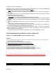
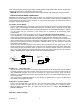
6 PIN HEAVY GAUGE WIRE HARNESS E9 IN REV.
20A Red: Remote Start Power 1 20A Red: Remote Start Power 2 Violet: Starter (+) Output Pink: Ignition 2 (+) Output Yellow: Ignition 1 (+) Output Brown: Acc/Heater (+) Output 5 PIN WIRE HARNESS Red/White: Parking Light Relay Power Input White: Parking Light Relay Output Black: System Main Ground (-) Brown: Siren (+) Output Red: 12v + Battery Power 3 PIN, DOOR LOCK CONNECTOR 1. Blue Wire ( - ) Unlock Pulse (+) Lock Pulse 3. Green Wire ( - ) Lock Pulse ( + ) Unlock Pulse WIRING E9 IN REV.
Keep wiring away from moving engine parts, exhaust pipes and high-tension cable. Be sure to tape wires that pass through holes on the firewall to prevent fraying. CAUTION: Do not connect the wire harness to the control module until all wiring to vehicle is complete. 6 PIN HEAVY GAUGE WIRING CONNECTIONS: Remember that what the system does to start a vehicle is to duplicate the functions of the ignition key switch! Below, we will explain the three basic functions of the ignition switch.
Some vehicles have [2] ignition wires that must be power. Connect the PINK wire to the ignition 2 wire from the ignition switch. The ignition wire should receive “12 volts” when the ignition key is in the “ON” or “RUN” and “START” or “CRANK” position. When the ignition is turned “OFF”, the ignition wire should receive “0” voltage. If the PINK wire is not used, cap the end of the wire.
RED WIRE — SYSTEM POWER (+12V CONSTANT) — The RED wire supplies power to the system. Connect this wire to a stable constant +12 volt source. H5. 3-PIN BLACK CONNECTOR. – TWO-WAY TRANSCEIVER/ANTENNA MODULE The Two-way transceiver/antenna mounting location should be the upper left or lower left corner of driver’s windshield. For optimum range we suggest that the antenna be mounted Antenna tip facing down. Warning! Do not mount in such a manner that it obstructs the driver’s view.
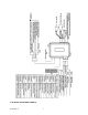
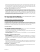
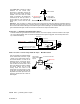
IN4003 Diode 87 H2/1 Blue / Black wire from control module 86 85 87a 30 H1/4 Yellow wire (Ignition 1 output) form Heavy Gauge wire harness Cut “Off” “On” “Acc” X To Ignition Coil “Start” Violet wire – Positive Door Switch Sensing Input (Zone 3)– This wire is the positive trigger input wire for positive door pin switch. This wire is connection for "positive" type factory door pins(typical FORD MOTOR). Locate the "common wire" for all door pins and make the connection of the VIOLET Wire here.
When the BLACK/WHITE wire is grounded, the remote start unit is operable. When this wire is open from ground, the remote start is disabled. 1. The optional “remote start toggle switch” can be added on to temporarily disable the Remote Start Device, it can prevent the vehicle from being remote started accidentally. This feature is useful if the vehicle is being serviced or stored in an enclosed area. To disable the remote start, move the optional remote start enable toggle switch to the OFF position.
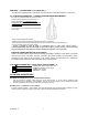
The Yellow wire provides an instant shutdown for the remote start, Hood Pin Switch whenever it is grounded. Connect the wire to the hood pin switch previously installed. This wire must be routed though a grommet in the firewall and To: White/black wire / To: Alarm instant connected to the hood pin switch. If Negative safety trigger Blue wire the pin switch is to be used with an alarm system, connect this wire with Diode Diode diode.
This wire provides a 200mA (-) ground output that becomes active and remains grounded while running. Ignition 3 output: Some newer vehicles use a third 87 ignition wire which is required to start Yellow Wire and keep the vehicle’s engine running. 87a 86 85 If this is the case, wire an IGN 3 relay 30 (not supplied) as shown below: Do not connect any vehicle circuits together, they are isolated for a reason.
This output is programmable. If programmed rearm a factory installed security system. This wire will supply a pulse whenever the remote start times out or is shut dowm using the transmitter and remote door locking. White / Blue wire – (-) Instant Start & Turn Off Input – This wire activates and turns off the remote starter each time it sees a momentary ground signal. Normally used for testing during installation or when activating the module from an after-market system.
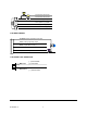
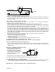
3 PIN DOOR LOCK CONNECTOR: (Maximum 500mA Output) NEGATIVE TRIGGER DOOR LOCK SYSTEM Blue Wire Blue Wire Door Unlock ( - ) Unlock Pulse (+) Lock Pulse Red(not used) Green Wire Door Lock ( - ) Lock Pulse Green Wire ( + ) Unlock Pulse To Exiting Door Lock Relay POSITIVE TRIGGER DOOR LOCK SYSTEM 5-WIRE ALTERNATING DOOR LOCK Master Door Lock Switch 86 87 3 Pin Plug To Alarm Blue Wire Door lock +12V Green Wire 87a 85 Green Wire Door Unlock X + 12V Splice To Exiting Door Lock Relay Red +12V 86
2 STEP DOOR UNLOCK WIRE CONNECTION FOR 2 STEP DOOR UNLOCK WIRE CONNECTION FOR GROUND SWITCHED DOOR LOCKS POSITIVE SWITCHED DOOR LOCKS H2/13: 22-Pin Plug From Alarm +12V OEM Door Master Lock Switch White/Green Wire Unlock Lock OEM Door Master Lock Switch 87 White/Green Wire Unlock 86 87a Existing Neg. Lock Wire Unlock Wire Lock 85 Existing Pos. Unlock Wire 30 Existing Neg. Green Wire Door Lock H2/13: 22-Pin Plug From Alarm + 12V Existing Pos.
4 All Confirmation chirps on 5 + 6 + 7 + 8 9 + + Siren Confirmation chirp on only Panic with Ignition off Panic with Ignition on & off With Alarm Function Without Alarm Function Without Car-jack mode Active Car-jack With Dome light turns on & off after ignition on & off (45 second door by-pass) Lock/Arm & Unlock/Disarm Confirmation Chirp With Dome light turns on after ignition off (45 second door by-pass) mode Horn Confirmation chirp on only Panic with Ignition on & off.
Five Chirps = 0.8 second Lock, double 0.8 second. Unlock Six Chirps = Double 0.8 second Lock, 0.8 second Unlock Seven Chirps = Door lock with “Comfort Feature” Eight Chirps = DBI Two step unlock ( DBI ONLY )** Nine chirps = DBI Unlock ALL doors ( DBI Only )** **Select either of these options when using Encore Two Way Data Bus Interface Only.
2 Push the Valet switch 5times (holding in on the 5th push) until one long chirp is heard then release the valet switch. You are now in the Alarm feature “C” programming mode. 3 Press and release the transmitter button corresponding to the feature you want to program.
2. 3. Press and hold the valet switch, the timer will immediately start. When the desired interval has passed, release the valet switch. 1 long chirp for confirmation. (Set to any interval between 1 second and 2 minutes) Note 1: If your built-in timer controls window/sunroof closure in your car DO NOT change the timer setting! This requires installer-only programming. Changing the value will adversely effect operation and may cause damage.
1. Turn the Ignition 'switch ‘ON/OFF’ 3 TIMES and stay in OFF position. th 2. Push the Valet switch 6 times (holding in on the 6 push) until one long chirp is heard then release the valet switch. You are now in the Start feature “D” programming mode. 3. Press and release the transmitter button corresponding to the feature you want to program.
3. Press and release the transmitter button corresponding to the feature you want to program. Press Transmitter Button 1 2 + One Chirp / LED one pulse Two Chirps / Three Chirps / Four Chirps / Factory Default LED two pulse LED three pulse LED four pulse Setting Exit the programming mode. (3 long chirp & 3 parking light flashes to confirm this exit.
1. Press button once on the transmitter to start the vehicle. 2. If everything goes well: a. Press button once on the transmitter to stop engine running. You have been completed this programming successfully. b. Press button on the transmitter to exit the program mode. There will be 3 long chirps & 3 parking light flashes for confirmation. 3. If the crank time is too long, (Engine already successfully running, but still cranks): a. Press once on the transmitter to stop engine running or press brake pedal.
3. Press the transmitter and buttons at the same time to set the “Timer Checking Type”. [3] LED flashes, [3] chirps to confirm this setting Once you complete step 3, you can adjust and test “Start Timer” as below: START TIMER PROGRAMMING: (TEST) and ADJUST) While the system is in Start Feature “E” programming mode, button once on the transmitter to start the vehicle. 1. Press the 2. If everything goes well: a. Press the ' button once on the transmitter to stop engine running.
4. Press the first, within 3 seconds press and hold the and buttons at the same time on the transmitter for 6 seconds, there will be a confirmation six chirp with 4 long chirp to confirm the system “Start Feature D & E Programming all returns to factory default setting. Exit: Turn Ignition to 'ON' position, or leave it for 15 seconds. A 3 long chirps & 3 parking light flashes to confirm exit. DATA BUS RESET FOR C I 3 INTERFACE 1. Turn the ignition ON then OFF 3 TIMES and stay in OFF position. 2.
1. Test the BRAKE shutdown circuit: With the vehicle in park (P), start the vehicle using the remote transmitter. Once the engine is running, press the brake pedal. The vehicle should shut down immediately. If the vehicle continues to run, check the brake circuit White/Violet wire connection. 2. Test the HOOD PIN shutdown circuit: Start the vehicle using the remote transmitter, Once the engine is running, pull the hood release and raise the hood. The vehicle should shut down immediately.
explained to the operator as it is in contrast to the normal operation of a vehicle utilizing an electrical neutral start switch and is inconsistent with the operation manual. Additional information concerning Key in Sensor methods 1&2 are listed below and should be reviewed before considering either alternative.
ENCORE LIMITED LIFETIME WARRANTY PROVISIONS ( U.S. ,Continental U.S. and Canada Only) 1. Encore Automotive Systems LLC. WARRANTS that this new unit has been thoroughly inspected and tested at the factory prior to delivery.
**IMPORTANT NOTE: Any damages resulting from an installation performed by anyone other than a professional installation technician authorized by Encore will void the product’s Limited Lifetime Warranty. It is the purchaser’s responsibility to register this product for any future warranty service. Warning: Some batteries may contain Perchlorate What is Perchlorate? Perchlorate is both a naturally occurring and manmade contaminant increasingly found in groundwater, surface water and soil.