
Installation manual

E9 IN REV. A
6
Some vehicles have [2] ignition wires that must be power. Connect the PINK wire to the ignition 2 wire
from the ignition switch. The ignition wire should receive “12 volts” when the ignition key is in the “ON”
or “RUN” and “START” or “CRANK” position. When the ignition is turned “OFF”, the ignition wire should
receive “0” voltage. If the PINK wire is not used, cap the end of the wire.
Brown Wire –Accessory Output (Heater /AC Output)
Connect the BROWN wire to the accessory wire in the vehicle that powers the climate control system.
An accessory wire will show + 12 volts when the ignition switch is turned to the “ACCESSORY” or “ON”
and “RUN” positions, and will show 0 Volts when the key is turned to the “OFF” and “START” or
“CRANK” position. There will often be more than one accessory wire in the ignition harness. The
correct accessory wire will provide power to the vehicle’s climate control system. Some vehicles may
have separate wires for the blower motor and the air conditioning compressor. In such cases, it will be
necessary to add a relay to power the second accessory wire.
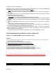
RS232 Two way SERIAL DATA PORT CONNECTION:
This connector is to be used for Serial Data communications with idatalink modules by Encore
only! DO NOT CONNECT THIS TO ANY OTHER WIRING!
This port will only operate correctly with Encore idatalink Modules
.
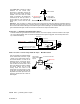
2 PIN WHITE CONNECTOR (THE LED STATUS INDICATOR):
The led indicator status should be mounted in a highly visible area such as top of the dashboard, on top
of the shifter console or on the dashboard face. Leave at least 6mm space behind the mounting location
for LED housing. Once a suitable location is chosen, drill a 6mm hole. Run the LED wires through the
hole then press the 2 pin LED housing into place. Route the LED wires to the control module.
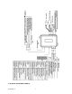
5 PIN WIRE HARNESS:
RED / WHITE WIRE –PARKING LIGHT RELAY INPUT —
The RED/WHITE wire is the input to the flashing parking light relay. The connection of the RED/WHITE
wire will determine the output polarity of the flashing parking light relay.
If the vehicle you are working on has +12volt switched parking lights, you don’t need connect this wire.
This wire is already connected to +12volt.
If the vehicle’s parking lights are ground switched, cut the RED/WHITE wire, connect the RED/WHITE
wire to chassis ground.
WHITE WIRE — PARKING LIGHT RELAY OUTPUT
(+12 V 10A OUTPUT) —
Connect the WHITE wire to the parking light wire coming from the headlight switch. Do not connect the
WHITE wire to the dashboard lighting dimmer switch. (Damage to the dimmer will result). The limitation
of the WHITE wire is 10 AMP max. Do not exceed this limit or damage to the alarm and parking relay
will result.
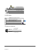
BLACK WIRE — SYSTEM GROUND –
This is the main ground connection of the alarm module. Make this connection to a solid section of the
vehicle frame. Do not connect this wire to any existing ground wires supplied by the factory wire loom,
make the connection to the vehicle’s frame directly.
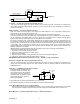
BROWN WIRE – (+) SIREN OUTPUT –
This wire is provides power to the supplied siren. Connect the Brown wire to the Red wire of the siren.
Connect the Black wire of the siren to a stable chassis ground.