ENMGS-16+2 16-Port 10/100/1000Mbps Web-Smart Gigabit Ethernet Switch 16 x 10/100/1000 Mbps RJ-45 Ports 2 x 1000Mbps mini-GBIC ports User’s Guide
FCC Warning ENMGS-16+2 has been tested and found to comply with the regulations for a Class A digital device, pursuant to Part 15 of the FCC Rules. These limits are designed to provide reasonable protection against harmful interference when the equipment is operated in a commercial environment. This equipment generates, uses, and can radiate radio frequency energy and, if not installed and used in accordance with this user’s guide, may cause harmful interference to radio communications.
UL Warning a) Elevated Operating Ambient Temperature- If installed in a closed or multi-unit rack assembly, the operating ambient temperature of the rack environment may be greater than room ambient. Therefore, consideration should be given to installing the equipment in an environment compatible with the manufacturer's maximum rated ambient temperature (Tmra).
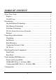
TABLE OF CONTENT About This Guide................................................................................. 1 Purpose ............................................................................................ 1 Terms/Usage .................................................................................... 1 Introduction.......................................................................................... 3 Gigabit Ethernet Technology ...........................................................
Installing the Web Management Utility......................................... 18 Discovery List................................................................................ 19 Monitor List ................................................................................... 20 Device Setting................................................................................ 22 Toolbar........................................................................................... 24 Configuring the Switch .........
System Reboot ........................................................................... 50 Logout............................................................................................ 50 Technical Specifications ....................................................................
ABOUT THIS GUIDE Congratulations on your purchase of the ENMGS-16+2. This device integrates 1000Mbps Gigabit Ethernet, 100Mbps Fast Ethernet and 10Mbps Ethernet network capabilities in a highly flexible package. Purpose This guide discusses how to install your ENMGS-16+2. Terms/Usage In this guide, the term “Switch” (first letter upper case) refers to your ENMGS-16+2, and “switch” (first letter lower case) refers to other Ethernet switches.
INTRODUCTION This chapter describes the features of the ENMGS-16+2 and some background information about Ethernet/Fast Ethernet/Gigabit Ethernet switching technology. Gigabit Ethernet Technology Gigabit Ethernet is an extension of IEEE 802.
In addition, the phenomenal bandwidth delivered by Gigabit Ethernet is the most cost-effective method to take advantage of today and tomorrow’s rapidly improving switching and routing internetworking technologies.
Switching Technology Another approach to pushing beyond the limits of Ethernet technology is the development of switching technology. A switch bridges Ethernet packets at the MAC address level of the Ethernet protocol transmitting among connected Ethernet or Fast Ethernet LAN segments. Switching is a cost-effective way of increasing the total network capacity available to users on a local area network.
VLAN (Virtual Local Area Network) A VLAN is a group of end-stations that are not constrained by their physical location and can communicate as if a common broadcast domain, a LAN. The primary utility of using VLAN is to reduce latency and need for routers, using faster switching instead. Other VLAN utility includes: Security, Security is increased with the reduction of opportunity in eavesdropping on a broadcast network because data will be switched to only those confidential users within the VLAN.
512 KB packet buffer Supports IEEE 802.3x flow control for full-duplex mode ports Supports IEEE 802.1Q VLAN Supports IEEE 802.
UNPACKING AND INSTALLATION This chapter provides unpacking and installation information for the Switch. Unpacking Open the shipping cartons of the Switch and carefully unpacks its contents.
Leave at least 10cm of space at the front and rear of the hub for ventilation. Install the Switch on a sturdy, level surface that can support its weight, or in an EIA standard-size equipment rack. For information on rack installation, see the next section, Rack Mounting. When installing the Switch on a level surface, attach the rubber feet to the bottom of each device. The rubber feet cushion the hub and protect the hub case from scratching. Figure 1.
Rack Mounting The switch can be mounted in an EIA standard-size, 19-inch rack, which can be placed in a wiring closet with other equipment. Attach the mounting brackets at the switch’s front panel (one on each side), and secure them with the provided screws. Figure 2. Combine the Switch with the provided screws Then, use screws provided with the equipment rack to mount each switch in the rack. Figure 3.
Connecting Network Cable The Switch supports 1000Mbps Gigabit Ethernet that runs in Autonegotiation mode and 10Mbps Ethernet or 100Mbps Fast Ethernet that runs both in half and full duplex mode and 1000Mbps Gigabit Ethernet runs in full duplex mode using four pairs of Category 5 cable. These 1000BASE-T ports are Auto-MDI type port. The Switch can auto transform to MDI-II or MDI-X type, so you can just make an easy connection that without worrying if you are using a standard or crossover twisted-pair cable.
IDENTIFYING EXTERNAL COMPONENTS This chapter describes the front panel, rear panel, and LED indicators of the Switch. Front Panel The figure below shows the front panels of the Switch. Figure 4. Front panel LED Indicators: Comprehensive LED indicators display the status of the switch and the network (see the LED Indicators chapter below).
Combo mini-GBIC Ports (Port 15~16) The Switch is equipped with two combo mini-GBIC ports, supported optional 1000BASE-SX/LX mini-GBIC module. The 1000BASE-T port 15 and 16 are the same ports with the miniGBIC port 15 and 16, when plug in the mini-GBIC module, the device will activate mini-GBIC, and the RJ45 port will be disabled. Rear Panel The rear panel of the Switch consists of an AC power connector and Reset button. The following shows the rear panel of the Switch. Figure 5.
UNDERSTANDING LED INDICATORS The front panel LEDs provides instant status feedback, and, helps monitor and troubleshoot when needed. Figure 6. LED indicators Power and System LEDs POWER: Power Indicator On : When the Power LED lights on, the Switch is receiving power. Off : When the Power turns off or the power cord has improper connection. SYSTEM: Management Indicator Blinking : When the CPU is working, the System LED is blinking. On/Off : The CPU is not working.
1000BASE-T Port 1~16 Status LEDs Link/ACT: Link/Activity On : When the Link/ACT LED lights on, the respective port is successfully connected to an Ethernet network. Blinking : When the Link/ACT LED is blinking, the port is transmitting or receiving data on the Ethernet network. Off : No link. 1000Mbps On : When the 1000Mbps LED lights on, the respective port is connected to a 1000Mbps Gigabit Ethernet network.
Combo mini-GBIC Port 15~ 16 Status LEDs Link/ACT On : When the fiber line connected to the mini-GBIC module is installed and connected to a network, the Link/ACT LED will lights on. Blinking : When the Link/ACT LED is blinking, the port is transmitting or receiving data on the Gigabit Ethernet network. Off Fiber line or mini-GBIC module is not installed. : 1000Mbps On : When the 1000Mbps LED lights on, the respective port is connected to a 1000Mbps Gigabit Ethernet network.
CONFIGURATION Through the Web Browser you can configure the Switch such as VLAN, Port Trunking, Jumbo Frame… etc. With the attached Web Management Utility, you can easily discover all the Web Management Switch, assign the IP Address, changing the password and upgrading the new firmware. Installing the Web Management Utility The following gives instructions guiding you through the installations of the Web Management utility. 1. 2. 3. 4. 5. Insert the Utility CD in the CD-Rom Drive.
Figure 7. Web Management Utility The Web Management Utility was divided into four parts, Discovery List, Monitor List, Device Setting and Toolbar function, for details instruction, follow the below section. Discovery List This is the list where you can discover all the Web management devices in the entire network. By pressing the “Discovery” button, you can list all the Web Management devices in the discovery list.
System word definitions in the Discovery List: z z z z z z z z z z MAC Address: Shows the device MAC Address. IP Address: Shows the current IP address of the device. Protocol version: Shows the version of the Utility protocol. Product Name: Shows the device product name. System Name: Shows the appointed device system name. DHCP: Shows the DHCP status of the device. Location: Shows where the device is located. Trap IP: Shows the IP where the Trap to be sent.
View Trap: The Trap function can receive the events that happen from the Web Management Switch in the Monitor List. There is a light indicator behind the “View Trap” button, when the light indicates in green, it means that there is no trap transmitted, and else when it indicates in red, it means that there is new trap transmitted, this is to remind us to view the trap. (Figure 8) Figure 8.
Device Setting You can set the device by using the function key in the Device Setting Dialog box. Configuration Setting: In this Configuration Setting, you can set the IP Address, Subnet Mask, Gateway, Set Trap to (Trap IP Address), System name, Location and DHCP function.
Figure 11. Password Change Firmware Upgrade: When the device has a new function, there will be a new firmware to update the device, use this function to update. Figure 12. Firmware Upgrade Access Web: Double click the device in the Monitor List or select a device in the Monitor List and press this “Web Access” button to access the device in Web browser. DHCP Refresh: Press this “DHCP Refresh” button to refresh IP address of selected device form DHCP server.
Toolbar The toolbar in the Web Management Utility have four main tabs, File, View, Options and Help. In the “File TAB”, there are Monitor Save, Monitor Save As, Monitor Load and Exit. z Monitor Save: To record the setting of the Monitor List to the default, when you open the Web Management Utility next time, it will auto load the default recorded setting. z Monitor Save As: To record the setting of the Monitor List in appointed filename and file path.
Configuring the Switch The 16-Port 10/100/1000Mbps Web-Smart Gigabit Ethernet Switch has a Web GUI interface for smart switch configuration. The Switch can be configured through the Web Browser. A network administrator can manage, control and monitor the switch from the local LAN.
Or through the Web Management Utility, you do not need to remember the IP Address, select the device shown in the Monitor List of the Web Management Utility to settle the device on the Web Browser. When the following dialog page appears, remain enter the default password "admin" and press Login to enter the main configuration window. Figure 14. Login After entering the password, the main page comes up, the screen will display the device status. Figure 15.
Configuration Menu When the main page appears, find the Configuration menu in the left side of the screen (Figure 16). Click on the setup item that you want to configure. There are sixteen options: Port Setting, IEEE 802.1Q VLAN Settings, Trunk Setting, Mirror Setting, IEEE 802.
Configuration Setting Find that there are seven items, including Port Setting, IEEE 802.1Q VLAN Settings, Trunk Setting, Mirror Setting, IEEE 802.1p Default Priority, Broadcast Strom Control Setting, Jumbo Frame Setting in Setup menu. Port Settings In Port Settings menu (Figure 17), this page will show each port’s status, selected drop down menu to set each port’s Speed, and QoS priority then press “Apply” button to activate changes.
The 1000BASE-T connections can operate in Forced Mode settings (1000M Full, 100M Full, 100M Half, 10M Full, 10M Half), Auto, or Disable. The default setting for all ports are Auto. The mini-GBIC (Gigabit Fiber) connections can operate in Forced Mode settings (1000M Full), Auto, or Disable Flow Control: This setting determines whether or not the Switch will be handling flow control. Set Flow Control to Enable for avoiding data transfer overflow.
IEEE 802.1Q VLAN A VLAN is a group of ports that can be anywhere in the network, but communicate as though they were in the same area. VLANs can be easily organized to reflect department groups (such as R&D, Marketing), usage groups (such as e-mail), or multicast groups (multimedia applications such as video conferencing), and therefore help to simplify network management by allowing users to move devices to a new VLAN without having to change any physical connections. IEEE802.
Asymmetric VLAN IEEE 802.1Q Asymmetric VLAN default setting is “Disabled”, you can press “Enabled” ratio button and Apply it to submit the Asymmetric VLAN function. (Figure 18) Figure 18. Enabled Asymmetric VLAN function Figure 19. Change setting warning message Note: The Settings of VLAN and Forwarding Table will be reset to default.
Untag VLAN Setting: The IEEE 802.1Q VLAN Configuration page provides powerful VID management functions. The original default VLAN setting has the VID as 01, named “default”, and contains all ports as “Untagged”. Figure 20. 802.1Q VLAN Setting Add VID: Click to create a new VID group, assigning ports from 01 to 16 as Untag, Tag, or Not Member. A port can be “Untagged” in only one VID. To save the VID group, press Apply. Figure 21.
VID: A unique VLAN ID. VLAN Name: A VLAN name can be setting as user wish. Port: The switch port number. Untag: Outgoing frames without VLAN tag. Tag: Outgoing frames with VLAN tag. Not Member: The port number which not to be grouped. Select All: Select all ports to be VLAN members or not VLAN members. Cancel: To call the modifications off. Apply: To activate and save the modifications. Figure 22. Delete VID Delete: Click to delete selected VID.
To change exist VLAN setting, press the VID to modify it. Figure 23. Modify VID Figure 24. Modify VID PVID settings: While receiving an untagged frame from the port, the switch will assign a tag to the frame, using the PVID of the port as its VID. Figure 25.
Here is an example of two VLAN groups with several ports on each group and VLAN 1 (VID 01) does not have communication with VLAN 2 (VID 02). Example1: Figure 26. Untag VLAN setting example Step1: Set VLAN1 member port 9~16 to “Not Member”, then apply setting. Step2: Create VID 2 and set port 9~16 to “Untag Port” member, then apply setting.
802.1Q Asymmetric VLAN settings example: Port 1~16 in VLAN 1, port1~5 in VLAN 2, port1,6~9 in VLAN 3. All VLAN1~3 have access to Internet via port 1. Note: The multi-need server must be support IEEE 802.1Q VLAN Example2: Figure 27. Asymmetric VLAN setting example Step1: Enable Asymmetric VLAN function. Step2: Add VID2 and set port 1~5 to “Untag Port” member, then apply setting. Step3: Add VID3 and set port1 and Port 6~9 to “Untag Port” member, then apply setting.
Tag VLAN Setting The IEEE802.1Q protocol defines a new format of the frame; it adds a tag header in the original Ethernet frame, as follows: IEEE802.1Q Tag VLAN is divided by VLAN ID (VID). On receiving a frame, the switch checks the VID in the tag header of the frame to decide which VLAN it belongs to. If the receiving frame doesn’t contain the tag header, the switch will assign a tag to the frame, using the PVID of the port as its VID. Figure 29.
Example3: Figure 30. Tag VLAN setting example Step1: Set VLAN1 member port1 to “Tag Port” and port 9~16 to “Not Member”, then apply setting. Step2: Add VID2 and set port1 to “Tag Port” and Port 9~16 to “Untag Port” member, then apply setting. Note: The multi-need server must be support IEEE 802.1Q VLAN, the sever uplink port is port1.
Another example is about setting tag VLAN with two switches. Switch 1’s VLAN 1 (2 ~ 3 ports) have access to the Switch 2’s VLAN 1 (2 ~ 3 ports). Example4: Figure 31. Tag VLAN setting example The settings of VLAN group for two devices are same. Step1: Set Switch1’s VLAN1 member port 1and 4~15 to “Not Member”, then apply setting. Step2: Set Switch2’s VLAN1 member as Switch1. Step3: Uplink two switches via Port 16.
Trunk Setting The Trunking function enables the cascading of two or more ports for a combined larger bandwidth. Up to six Trunk groups may be created, each supporting up to 8 ports. Add a Trunking Name and select the ports to be trunked together, and click Apply to activate the selected Trunking groups. Figure 32. Trunk Configuration Be sure that the selected trunk setting port must connect to the device with a same VLAN group.
Mirror Setting Port Mirroring is a method of monitoring network traffic that forwards a copy of each incoming and/or outgoing packet from one port of the Switch to another port where the packet can be studied. This enables network managers to better monitor network performances. Figure 33. Mirror Setting Selection of the Sniffer mode is as follow: TX (transmit) mode: this mode will duplicate the data transmit from the source port and forward to the Sniffer port.
IEEE 802.1p Default Priority This feature displays the status Quality of Service priority levels of each port, and for packets that are untagged, the switch will assign the priority in the tag depending on your configuration. Figure 34. IEEE 802.
Broadcast Storm Control Setting The Broadcast Storm Control feature provides the ability to control the receive rate of broadcasted packets. If Enabled (default is Disabled), threshold settings of 8,000 ~ 4,096,000 bytes per second can be assigned. Press Apply for the settings to take effect. Figure 35. Broadcast Storm Control Setting Jumbo Frame Setting Jumbo Frames enable the transportation of identical data in fewer frames. This ensures less overhead, lower processing time, and fewer interruptions.
System Setting Find that there are nine items, including System Information, System Setting, Trap Setting, Password Setting, Statistics, Factory Reset, Backup Setting, Firmware Upload and System Reboot in System menu.
System Setting The System Setting includes IP Information and System information. There are two ways for the switch to attain IP: Static and DHCP (Dynamic Host Configuration Protocol). When using static mode, the IP Address, Subnet Mask and Gateway can be manually configured. When using DHCP mode, the Switch will first look for a DHCP server to provide it with an IP address, network mask, and default gateway before using the default or previously entered settings. By default the IP setting is static mode.
Trap Setting By configuring the Trap Setting, it allows Web Management Utility to monitor specified events on this Web-Smart Switch. By default, Trap Setting is Disabled. When the Trap Setting is Enabled, enter the Destination IP address of the managing PC that will receive trap information. Figure 39. Trap Setting System Events: Monitoring the system’s trap. Device Bootup: a trap when booting up the system.
Password Setting Setting a password is a invaluable tool for managers to secure the Web Smart Switch. After entering the old password and the new password two times, press Apply for the changes to take effect. If you forget the password, press the “Reset” button in the front panel of the Switch, the current setting includes VLAN, Port Setting… etc. will be lost and the Switch will restore to the default setting. Figure 40.
Refresh: To renew the details collected and displayed. Clear Counter: To reset the details displayed. To view the statistics of individual ports, click one of the Port ID as Figure . Figure 42. Port Statistics Factory Reset The Factory Reset helps you to reset the device back to the default setting from the factory. All of the configuration will be reset, the IP address of the device will be set to default setting 192.168.1.1. Figure 43.
Backup Setting The backup setting help you to backup the current setting of the Switch. Once you need to backup the setting, press the “Backup” button to save the setting. To restore a current setting file to the device, you must specify the backup file and press “Restore” button to proceed the setting of the recorded file. Figure 44. Backup Setting Note: when restoring a recorded file, the current password will not be erased.
System Reboot Provides to a safe way to reboot the system. Ensure the configuration has been saved, or all the changes you just made may be lost after system reboot. Figure 46. System Reboot Logout When press this function, the web configuration will go back to first Login page. Figure 47.
TECHNICAL SPECIFICATIONS General Standards Protocol Data Transfer Rate Topology Network Cables Number of Ports IEEE 802.3 10BASE-T Ethernet IEEE 802.3u 100BASE-TX Fast Ethernet IEEE 802.3ab 1000BASE-T Gigabit Ethernet IEEE 802.3x Full Duplex Flow Control IEEE 802.3z 1000BASE-SX/LX Gigabit Ethernet CSMA/CD Ethernet: 10Mbps (half-duplex), 20Mbps (full-duplex) Fast Ethernet: 100Mbps (half-duplex), 200Mbps (full-duplex) Gigabit Ethernet: 2000Mbps (full-duplex) Star 10BASET: 2-pair UTP Cat.
Performance Transmits Method: RAM Buffer: Filtering Address Table: MAC Address Learning: Packet Filtering / Forwarding Rate: Store-and-forward 512KB per device 8K entries per device Automatic update 10Mbps Ethernet: 14,880/pps 100Mbps Fast Ethernet: 148,800/pps 1000Mbps Gigabit Ethernet: 1,488,000/pps 46