ENVCWI-PTG1 Wireless Network (IP) Camera with PAN & TILT Advanced Installation Guide Version 1.
Regulatory notes and statements Wireless LAN, Health and Authorization for use Radio frequency electromagnetic energy is emitted from Wireless LAN devices. The energy levels of these emissions however are far much less than the electromagnetic energy emissions from wireless devices like for example mobile phones. Wireless LAN devices are safe for use frequency safety standards and recommendations.
FCC Radio Frequency Exposure statement This Wireless LAN radio device has been evaluated under FCC Bulletin OET 65 and found compliant to the requirements as set forth in CFR 47 Sections 2.1091, 2.1093, and 15.247 (b) (4) addressing RF Exposure from radio frequency devices. The radiated output power of this Wireless LAN device is far below the FCC radio frequency exposure limits.
Safety Information Your device contains a low power transmitter. When device is transmitted it sends out radio frequency (RF) signal. CAUTION: To maintain compliance with FCC’s RF exposure guidelines, this equipment should be installed and operated with minimum distance 20cm between the radiator and your body. Use on the supplied antenna. Unauthorized antenna, modification, or attachments could damage the transmitter and may violate FCC regulations.
Copyright The company has an on-going policy of upgrading its products and it may be possible that information in this document is not up-to-date. Please check with your local distributors for the latest information.
P REFACE Thank you for purchasing the Wireless Network (IP) Camera with PAN & TILT, a powerful wireless network camera with the 2-way audio function which provides the high-quality image and on-the-spot audio via the Internet connection. The camera’s pan/tilt functions allow you to control the camera to monitor everywhere remotely. Through the GPIO connectors, the camera can attach a variety of external devices for your specific purposes.
Contents Preface................................................................................................5 Chapter 1 Introduction To Your Camera.............................................7 1.1 Checking the Package Contents...........................................7 1.2 Getting to Know Your Camera ..............................................8 1.3 Features and Benefits .........................................................10 1.4 System Requirement................................................
C HAPTER 1 I NTRODUCTION T O Y OUR C AMERA 1.1 Checking the Package Contents Check the items contained in the package carefully. You should have the following: One Wireless Network (IP) Camera with PAN & TILT. One AC Power Adapter. One External Detachable Antenna One Wall Mount Kit. One GPIO Connector One Ethernet Cable (RJ-45 type). One Installation CD-ROM. One Quick Installation Guide. NOTE Once any item contained is damaged or missing, contact the authorized dealer of your locale.
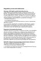
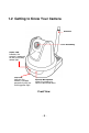
1.2 Getting to Know Your Camera Antenna Lens Assembly Power LED indicates the camera is powered on with the steady amber light. Link LED indicates the camera’s network connectivity with the flashing green light. Internal Microphone allows the camera to receive sound and voice.
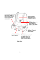
Ethernet Cable Connector connects the network cable, which supports the NWay protocol so that the camera can detect the network speed automatically. External Antenna Connector connects the external antenna. DC Power Connector connects the AC power adapter, in order to supply power to the camera. Audio-out Connector connects an external active speaker. GPIO Connectors is used to connect the external devices.
1.3 Features and Benefits MJPEG codec Supported The camera provides you with excellent images by the MJPEG codec technology, allowing you to adjust image size and quality, and bit rate according to the networking environment. 2-way Audio Capability The built-in microphone of the camera provides on-the-spot audio via the Internet, allowing you to monitor the on-site voice. In addition, you can connect an external speaker to the camera to speak through the camera.
Multiple Platforms Supported The camera supports multiple network protocols, including TCP/IP, SMTP e-mail, HTTP, and other Internet related protocols. Therefore, you can use the camera in a mixed operating system environment, such as Windows 2000 and Windows XP. Multiple Applications Supported Through the remote access technology, you can use the cameras to monitor various objects and places for your own purposes. For example, babies at home, patients in the hospital, offices and banks, and more.
1.4 System Requirement Networking LAN: 10Base-T Ethernet or 100Base-TX Fast Ethernet. WLAN: IEEE 802.11g/b compliant wireless interface. Accessing the Camera using Web Browser Platform: Microsoft® Windows® 2000/XP/Vista CPU: Intel Pentium III 350MHz or above RAM: 128MB Resolution: 800x600 or above User Interface: Microsoft® Internet Explorer 6.0 or above Apple Safari 2 or above Mozilla Firefox 2.
C HAPTER 2 H ARDWARE I NSTALLATION 2.1 Installing the Wall Mount Kit The camera comes with a Wall Mount Kit, which allows you to place your camera anywhere by mounting the camera through the three screw holes located in the base of the Wall Mount Kit.
2.2 Connecting the Camera to LAN/WLAN Use the provided Ethernet cable to connect the camera to your local area network (LAN). When you connect the AC power adapter, the camera is powered on automatically. You can verify the power status from the Power LED on the front panel of the camera. Once connected, the Link LED starts flashing green light and the camera is on standby and ready for use now.
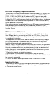
2.3 Applications of the Camera The camera can be applied in multiple applications, including: Monitor local and remote places and objects via Internet or Intranet. Capture still images and video clips remotely. Upload images or send email messages with the still images attached. The following diagram explains one of the typical applications for your camera and provides a basic example for installing the camera.
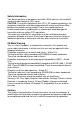
C HAPTER 3 A CCESSING T HE C AMERA 3.1 Using IPFinder The camera comes with a convenient utility, IPFinder, which is included in the Installation CD-ROM, allowing you to search the camera on your network easily. 1. Insert the Installation CD-ROM into your computer’s CD-ROM drive to initiate the Auto-Run program. 2. Click the IPFinder item to launch the utility. The control panel will appear as below. Display the connected camera(s). Double click to link the Camera.
3.2 Accessing to the Camera Whenever you want to access the camera: 1. Connect your camera to the network (or the PC directly). 2. Since the default configuration of the camera is DHCP mode enabled, you are recommended to launch IPFinder to search the IP address that is assigned to the camera by the DHCP server, and then click Link to access the camera via the Web browser. 3.
After you login into the Web Configuration of the camera, the main page will appear as below: Zoom In Buttons Live View/Setup Switch Nightmode Button Camera Information Pan/Tilt Buttons Live View Image Function Buttons The main page of the Web Configuration provides you with many useful information and functions, including: Camera Information – Displays the camera’s location and the current date & time. The information can be modified in the Web Configuration.
where you right-clicked will be displayed in the central part of Live View area. Zoom In Buttons – Click the buttons to zoom in the live view image by 1x, 2x, and 3x. Nightmode Button – Click the button to enable the “nightshot mode” to deliver clearer images in the dark environment. However, this will reduce the frame rate of video setting. Live View/Setup Switch – Click Setup to configure the camera. For details, see Chapter 4.
Function Buttons – Use these buttons to control the audio, video, and trigger functions. Manual Record allows you to record and save a video clip. Snapshot allows you to capture and save a still image. Browse allows you to assign the destination folder to store the video clips and still images. Talk allows you to speak out through the camera. Please note only one user is allowed to use this function at a time. Listen allows you to receive the on-site sound and voice from the camera.
3.3 Configuring the IP Address of the PC If you are failed to access to the camera, please check the IP address of your computer. When you connect the camera to your computer directly to proceed with configuration of the camera, you need to set up the IP addresses to be in the same segment for the two devices to communicate. 1. On your computer, click Start > Control Panel to open the Control Panel window. 2. Double-click Network Connection to open the Network Connection window. 3.
C HAPTER 4 C ONFIGURING T HE C AMERA 4.1 Using the Web Configuration You can access and manage the camera through the Web browser and the provided software application UltraView. This chapter describes the Web Configuration, and guides you through the configuration of the camera by using the Web browser. To configure the camera, click Setup on the main page of Web Configuration. The Web Configuration will start from the Basic page.
4.2 Using Smart Wizard The camera’s Smart Wizard lets you configure your camera easily and quickly. The wizard will guide you through the necessary settings with detailed instructions on each step. To start the wizard, click Smart Wizard in the left menu bar. Step 1. Camera Settings Enter the name for the camera and place. Enter the administrator password set. Step 2. IP Settings Select the IP setting according to your network: DHCP, Static IP, or PPPoE.
Step 3. Email Settings Enter the required information to be able to send email with image. Step 4. Wireless Networking Complete the required settings for wireless networking.
Step 5. Confirm Settings This step shows the configuration of your camera. When you confirm the settings, click Apply to finish the wizard and reboot the camera. Otherwise, click Prev to go back to the previous step(s) and change the settings. Or, click Cancel to end the wizard and discard the changes.
4.3 Basic Setup The Basic menu contains three sub-menus that provide the system settings for the camera, such as the Camera Name, Location, Date & Time, and User management. Basic >> System Basic - Camera Name: Enter a descriptive name for the camera. - Location: Enter a descriptive name for the location used by the camera. Indication LED This item allows you to set the LED illumination as desired. There are two options: Normal and OFF.
Basic >> Date & Time - TimeZone: Select the proper time zone for the region from the pull-down menu. - Synchronize with PC: Select this option and the date & time settings of the camera will be synchronized with the connected computer. - Synchronize with NTP Server: Select this option and the time will be synchronized with the NTP Server. You need to enter the IP address of the server and select the update interval in the following two boxes. - Manual: Select this option to set the date and time manually.
Basic >> User Administrator To prevent unauthorized access to the camera’s Web Configuration, you are strongly recommended to change the default administrator password. Type the administrator password twice to confirm and set the password. General User - User Name: Enter the user’s name you want to add to use the camera. - Password: Enter the password for the new user. When you are finished, click Add/Modify to add the new user to the camera.
- UserList: Display the existing users of the camera. To delete a user, select the one you want to delete and click Delete. Guest - User Name: Enter the guest’s name you want to add to use the camera. - Password: Enter the password for the new guest. - UserList: Display the existing guests of the camera. To delete a user, select the one you want to delete and click Delete. NOTE The “General User” can access the camera and control the Function buttons of the camera’s Web Configuration.
4.4 Network Settings The Network menu contains three sub-menus that provide the network settings for the camera, such as the IP Setting, DDNS Setting, IP Filter, and Wireless network.
This item allows you to select the IP address mode and set up the related configuration. The default setting is DHCP mode enabled. - DHCP: Select this option when your network uses the DHCP server. When the camera starts up, it will be assigned an IP address from the DHCP server automatically. - Static IP: Select this option to assign the IP address for the camera directly. You can use IPFinder to obtain the related setting values. IP Enter the IP address of the camera. The default setting is 192.168.0.30.
With the Dynamic DNS feature, you can assign a fixed host and domain name to a dynamic Internet IP address. Select the Enable option to enable this feature. Then, select the DDNS Provider from the pull-down list and enter the required information in the Host Name, User Name, and Password boxes. Please note that you have to sign up for DDNS service with the service provider first.
Network >> IP Filter The IP Filter setting allows the administrator of the camera to limit the users within a certain range of IP addresses to access the camera. Start/End IP Address Assign a range of IP addresses that are not allowed to access the camera by entering the Start IP address and End IP address. When you finish the setting, click Add to save the range setting. You can repeat the action to assign multiple ranges for the camera. For example, when you enter 192.168.0.
Deny IP List The list displays the range setting(s) of IP addresses that are not allowed to access the camera. To clear the setting, select a range of IP addresses from the list and click Delete. Network >> Wireless Setting The camera supports WLAN while you use the wireless network. Select the Enable option to enable this feature. - Network ID (SSID): Keep the default setting of this option to connect the camera to any access point under the infrastructure network mode.
specified access point, set a SSID for the camera to correspond with the access point’s ESS-ID. To connect the camera to an Ad-Hoc wireless workgroup, set the same wireless channel and SSID to match with the computer’s configuration. Click Site Survey to display the available wireless networks, so that you can easily connect to one of the listed wireless networks. List of searching results - Wireless Mode: Select the type of wireless communication for the camera: Infrastructure or Ad-Hoc.
authentication servers. The user has to manually enter the starting password in their access point or gateway, as well as in each PC on the wireless network. If you select Open or Shared-key as the Authentication mode, you need to complete the following settings: Encryption: Select the WEP option to enable the data encryption feature to secure the camera within the wireless network. Format: Once you enable the Encryption feature, you need to determine the encryption format by selecting ASCII or HEX.
4.5 Pan/Tilt Settings The Pan/Tilt menu allows you to configure the pan/tilt functions of the camera. Pan/Tilt >> Pan & Tilt Settings - Pan/Tilt Calibration: Click Calibration to calibrate the position of the camera lens. - Pan Steps: Set the changing range (1~20 degrees) when you click the Left/Right button. - Tilt Steps: Set the changing range (1~20 degrees) when you click the Up/Down button.
4.6 Setting up Video & Audio The Video & Audio menu contains three sub-menus that provide the video and audio settings for the camera. Video & Audio >> Camera Image Setting - Brightness: Adjust the brightness level from 0 ~ 100. - Contrast: Adjust the contrast level from 0 ~ 100. - Saturation: Adjust the colors level from 0 ~ 100.
Click Default to restore the default settings of the three options above. - Mirror: Select the Horizontal option to mirror the image horizontally. Select the Vertical option to mirror the image vertically. - Light Frequency: Select the proper power frequency according to the camera’s location: 50Hz, 60Hz, or Outdoor. Overlay Setting - Includes Date & Time: Select this option to display the date & time stamp on the live view image.
Video & Audio >> Video MJPEG - Video Resolution: Select the desired video resolution from the three formats: VGA, QVGA and QQVGA. The higher setting (VGA) obtains better video quality while it uses more resource within your network. - Video Quality: Select the desired image quality from five levels: Lowest, Low, Medium, High, and Highest. - Frame Rate: Select Auto or a proper setting depending on your network status.
Video & Audio >> Audio Camera Microphone In Select the Enable option to enable the camera’s audio function, so that you can receive the on-site sound and voice from the camera. Camera Speaker Out Select the Enable option to enable the camera’s external speaker function, so that the connected speaker can play the sound and voice through the camera. - Volume: Set the speaker’s volume.
4.7 Event Server Configuration The Event Server menu contains two sub-menus that allow you to upload images to FTP, send emails that include still images, and store the images to a NAS system. When you complete the required settings for FTP or Email, click Test to test the related configuration is correct or not. Once the camera connects to the server successfully, click Apply. Event Server Setting>> FTP - Host Address: Enter the IP address of the target FTP server.
- Directory Path: Enter the destination folder for uploading the images. For example, /Test/. - Passive Mode: Select the Enable option to enable passive mode. Event Server Setting >> Email - SMTP Server Address: Enter the mail server address. For example, mymail.com. - Sender Email Address: Enter the email address of the user who will send the email. For example, John@mymail.com. - Sender User Name: Enter the user name to login the mail server.
- Sender Password: Enter the password to login the mail server. - Receiver #1 Email Address: Enter the first email address of the user who will receive the email. - Receiver #2 Email Address: Enter the second email address of the user who will receive the email.
4.8 Motion Detect The Motion Detect menu contains the command and option that allow you to enable and set up the motion detection feature of the camera. The camera provides two detecting areas. To enable the detecting area, select Window 1 or 2 from the pulldown list, and then select Enable. When the detecting area is enabled, you can use the mouse to move the detecting area and change the area coverage. - Name: Assign a name to the detecting area.
4.9 Event Config The Event Config menu contains five sub-menus that provide the commands to configure event profiles. Event Configuration >> General Setting - Snapshot/Recording Subfolder: You can assign a descriptive name for the subfolder to save the captured image/video files. Otherwise, leave this option blank to use the default setting. - GPIO Trigger Out Retention Time Per Event: Limit the retention time of the GPIO Trigger Out function.
Event Configuration >> Arrange Schedule Profile This sub-menu displays the scheduled profile(s). To customize the profile, click Add and then enter a descriptive name for the profile in the prompt dialog window. After entering the profile name, click OK and the profile is added to the Schedule Profiles list. To delete the profile, select the profile in the list and click Delete. - Profile Name: Display the profile name that you select in the Schedule Profiles list.
Event Configuration >> Motion Detect Trigger Select the Enable option to enable the motion detect trigger function of the camera, so that you can set Trigger Out function or send captured images within the detecting area to the FTP server or email receiver. You have to configure corresponding settings, such as FTP server and email server, to enable this feature. - Schedule Profile: Select a schedule profile from the pull-down list.
Event Configuration >> Schedule Trigger You can separately configure the schedule for trigger function of the camera by Email or FTP. Select the Enable option on each item, and then select a Schedule Profile from the pull-down list and set the Interval time. Email/FTP Schedule - Schedule Profile: Select a schedule profile from the pull-down list. - Interval: Enter a number in this box to setup the time (in second) to send Email or upload to FTP regularly.
Event Configuration >> GPIO Trigger Select the Enable option to enable the GPIO trigger function of the camera, so that you can set Trigger Out function or send captured images within the detecting area to the FTP server or email receiver. You have to configure corresponding settings, such as FTP server and email server, to enable this feature. - Schedule Profile: Select a schedule profile from the pull-down list.
4.10 Tools The Tools menu provides the commands that allow you to restart or reset the camera. You can also backup and restore your configuration, and upgrade the firmware for the camera. Factory Reset Click Reset to restore all factory default settings for the camera. System Reboot Click Reboot to restart the camera just like turning the device off and on. The camera configuration will be retained after rebooting.
- Backup: Click Get the backup file to save the current configuration of the camera. - Restore: Click Browse to locate the backup file and then click Restore. Update Firmware This item displays the current firmware version. You can upgrade the firmware for your camera once you obtained a latest version of firmware. - Select the firmware: Click Browse to locate the backup file and then click Update. NOTE Make sure to keep the camera connected to the power source during the process of upgrading firmware.
4.11 Information The Information menu displays the current configuration and events log of the camera. Device Info Display the Basic, Video & Audio, Network, and Wireless settings of the camera. System Log The Logs table displays the events log recorded by the system.
A PPENDIX A.1 Specification Image Sensor Sensor Resolution 1/4” color CMOS 640x480 Video Compression Video resolution M-JPEG VGA/QVGA/QQVGA; 30fps max.
ROM Power Communication LAN WLAN 4MB NOR Flash DC 12V 10/100Mbps Fast Ethernet, auto-sensed, Auto-MDIX IEEE 802.11b/g Protocol support TCP/IP, UDP, ICMP, DHCP, NTP, DNS, DDNS, SMTP, FTP, PPPoE, UPnP Pan/Tilt Pan Tilt Software OS Support Browser Software Windows 2000/XP/Vista Internet Explorer 6.0 or above Apple Safari 2 or above Mozilla Firefox 2.
A.2 GPIO Terminal Application This is typically used in association with programming scripts for developing applications for motion detection, event triggering, alarm notification via e-mail, and a variety of external control functions. The GPIO connectors are located on the rear panel of the camera, which provide the interface of connecting the sensor device (IN) and controlled device (OUT).
A.3 Glossary of Terms NUMBERS 10BASE-T 100BASE-TX 10BASE-T is Ethernet over UTP Category III, IV, or V unshielded twisted-pair media. The two-pair twisted-media implementation of 100BASET is called 100BASE-TX. A ADPCM Adaptive Differential Pulse Code Modulation, a new technology improved from PCM, which encodes analog sounds to digital form. Applet Applets are small Java programs that can be embedded in an HTML page.
message, and medium. In networks, devices and application tasks and processes communicate messages to each other over media. They represent the sender and receivers. The data they send is the message. The cabling or transmission method they use is the medium. Connection In networking, two devices establish a connection to communicate with each other. D DHCP Developed by Microsoft, DHCP (Dynamic Host Configuration Protocol) is a protocol for assigning dynamic IP addresses to devices on a network.
network Ethernet area. The enterprise network serves the needs of a widely distributed company and operates the company’s mission-critical applications. The most popular LAN communication technology. There are a variety of types of Ethernet, including 10Mbps (traditional Ethernet), 100Mbps (Fast Ethernet), and 1,000Mbps (Gigabit Ethernet). Most Ethernet networks use Category 5 cabling to carry information, in the form of electrical signals, between devices.
which consists of 16 unique symbols: the numbers 0 to 9 and the letters A to F. For example, the decimal number 15 is represented as F in the hexadecimal numbering system. The hexadecimal system is useful because it can represent every byte (8 bits) as two consecutive hexadecimal digits. It is easier for humans to read hexadecimal numbers than binary numbers. I Intranet This is a private network, inside an organization or company that uses the same software you will find on the public Internet.
of its dedicated communication lines to companies or individuals who can’t afford the high monthly cost for a direct connection. J JAVA Java is a programming language that is specially designed for writing programs that can be safely downloaded to your computer through the Internet without the fear of viruses. It is an object-oriented multithread programming best for creating applets and applications for the Internet, Intranet and other complex, distributed network. L LAN Local Area Network.
Network NWay Protocol IP address. NAT distributes the responses to the proper IP addresses within your network. A network consists of a collection of two or more devices, people, or components that communicate with each other over physical or virtual media. The most common types of network are: LAN – (local area network): Computers are in close distance to one another. They are usually in the same office space, room, or building.
information between networks and forwarding data to its destination. Still other protocols dictate how data is transferred across the medium, and how servers respond to workstation requests and vice versa. Common network protocols responsible for the presentation and formatting of data for a network operating system are the Internetwork Packet Exchange (IPX) protocol or the Internet Protocol (IP).
SMTP SNMP Station Subnet mask The Simple Mail Transfer Protocol is used for Internet mail. Simple Network Management Protocol. SNMP was designed to provide a common foundation for managing network devices. In LANs, a station consists of a device that can communicate data on the network. In FDDI, a station includes both physical nodes and addressable logical devices. Workstations, single-attach stations, dual-attach stations, and concentrators are FDDI stations.
all access methods. It consists of several pairs of wires enclosed in an unshielded sheath. W WAN WEP Windows WPA WPA2 Wide-Area Network. A wide-area network consists of groups of interconnected computers that are separated by a wide distance and communicate with each other via common carrier telecommunication techniques. WEP is widely used as the basic security protocol in WiFi networks, which secures data transmissions using 64bit or 128-bit encryption.