
Datasheet


=
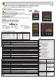
Band Alarm With Inhibition
A1tP. bAn.i.
ON
ON
OFF
OFF
Begining
of procedure
SV = et i
ASV =
(ASV min. = 0, ASV ma . = 300 )
S point of CONT output
Set point of AL1 output
x
Band alarm is possible
Band alarm is possible
Begining
of procedure
SV
SV
SV+ASV
SV+ASV
SV-ASV
SV-ASV
230V ACor 24V
Supply
Cable size: 1,5mm²
Holding screw
0.4-0.5Nm
Equipment is protected throughout
by DOUBLE INSULATION
Switch
Fuse
F 100 mA 250V AC
N
L
Fuse should
be connected
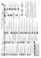
ALARM1 AND ALARM2 OUTPUT TYPES
CONNECTION DIAGRAM
J-K-T-S-R t t ermo upl :For ype h co e
Use suitable compensation cables. Don’t use
jointed cables. Pay attention to the polarities
of the thermocouple cables as shown in the
figure right are connected to the.
For r s ce h ee istan t ermomet r :
When 2 wired Pt 100 is used, terminals that are
shown at the right of there must be short
circuited for each product.
184-253V AC
50/60Hz 7VA
SUPPLY :
SENS :OR INPUT
NOT :E
ETC9420
ENDA ETCseriesareintendedforinstallationincontrolpanels.Makesurethatthedeviceisusedonlyforintendedpurpose. Theshielding
mustbegroundedontheinstrumentside.Duringaninstallation,allofthecablesthatareconnectedtothedevicemustbefreeofenergy.
Thedevicemustbeprotectedagainstinadmissiblehumidity,vibrations,severesoilingandmakesurethattheoperationtemperatureisnot
exceeded. Allinputandoutputlinesthatarenotconnectedtothesupplynetworkmustbelaidoutasshieldedandtwistedcables. These
cablesshouldnotbeclosetothepowercablesorcomponents. Theinstallationandelectricalconnectionsmustbecarriedonbyaqualified
staffandmustbeaccordingtotherelevantlocallyapplicableregulations
.
Logicoutputoftheinstrumentisnotelectrically
insulatedfromtheinternalcircuits. Therefore,
whenusingagroundingthermocouple,donot
connectthelogicoutputterminalstotheground.
1)Mainssupplycordsshallmeettherequirements
ofIEC60227orIEC60245.
2)Inaccordancewiththesafetyregulation,the
powersupplyswitchshallbringtheidentificationof
therelevantinstrumentanditshouldbeeasily
accessiblebytheoperator.
Note:
Independent Alarm
A1.tP. indE=
=
Deviation Alarm
A1.tP. DE.
Band Alarm
=A1.tP. bAnd
A.StA. Hi=
A1.St. boHi=
=A.StA. Lo
=A1.St. biHi
ASV
SV
SV
SV
SV+ASV
SV+ASV
SV-ASV
OFF
OFF
OFF
OFF
OFF
OFF
-300
300
+300
300
ON
ON
ON
ON
ON
ON
SV = ASV =Set point of CONT output Set point of alarm output
(ASV min. =-300, ASV max. = +300)
(ASV min. = 0, ASV max. = +300)
(
)
ASV min = beginning of scale
ASV max = end of scale
SV = ASV =Set point of CONT output Set point of AL1 output
a1.Hy. A1.Hy..
A1.Hy.
A1.Hy.
(If ,inP Pt..0= ASV min. = -30.0,
ASV max. = +30.0)
(If ,inP Pt..0= ASV min. = 0.0, ASV max. = +30.0)
MODIFICATION OF CONTROL AND ALARM SET POINTS
C.SEt
150
A1.sE.
250
C.SEt
150
A1.sE.
250
A1.sE.
249
First, press and hold key until the massage appears on the display. Then, the value is adjusted by using keys.C.Set
SET
CSET
SET
CSET
SET
CSET
SET
CSET
ASET
ASET
ASET
When is released, it
returns to normal operation.
CSET
When s released, it
returns to normal operation.
ASET i
130
150
PV
PV
PV
PV
PVPV
SV
SV
C.SEt
149
PV
SV
SV
SV
SV
SV
First, press and hold key, alarm setpoint value appears on the display. Then, the value is adjusted by using keys.
different from Alarm1 and Alarm2 setpoint values can be adjusted in sequence when per press key.
.
If C.ot.S out1.
ASET
ASET
SET
CSET
ASET
NOTE: The maximum of is the value of parameter and the minimum of it is the value of parameter.
If independent alarm is selected, values can be adjusted between the limits of the full scale.
If deviation alarm is selected, and values can be adjusted between
If band alarm is selected, and values can be adjusted between
C.SEt C.Hi.L. C.Lo.L.
A1.SE. and
- and + .
and + .
A2.SE.
A1.SE. A2.SE.
A1.SE. A2.SE.
300 300
0 300
- - - -
- - - -
PFA
150
PSC
150
PV PV
PV
PV
SV SV
SV
SV
Error Messages
Temperature value is
higher than the scale
Temperature value is
lower than the scale
Temperature sensor
is broken or over temperature
Pt 100 or a sensor
line is short circuited
150
150
15
16
17
18
19
20
21
10
11
12
11
12
13
14
15
16
17
15
16
17
18
19
20
21
10
11
12
11
12
13
14
15
16
17
8
9
10
ETC742 -230VAC0
ETC742 -20 4VAC
ETC842 -230VAC0
ETC942 -230VAC0
ETC842 -20 4VAC
ETC9420-24VAC
8
9
10
8
9
10
11
12
13
14
3
4
5
ETC442 -230VAC0
8
9
10
11
12
13
14
3
4
5
ETC442 -2 VAC0 4
-
-
+
+
CONT./AL2
Al1
AC 250V 2A
RESISTIVE
LOAD
AC 250V 2A
RESISTIVE
LOAD
230V AC
+10% -20%
50/60Hz 5VA
TC
Pt 100
RS-485 COM.
RS- 485
SSR
OUT
B
+
-
2
1
A
6
7
15
1
2
6
7
15
1
2
3
4
5
6
7
1
2
3
4
5
6
7
1
2
3
4
5
6
7
8
9
13
14
1
2
3
4
5
6
7
8
9
13
14
SSR
OUT
+
-
-
+
TC
Pt 100
CONT./AL2
AC 250V 2A
RESISTIVE
LOAD
Al1
AC 250V 2A
RESISTIVE
LOAD
24V AC ±10%
50/60Hz 7VA
-
+
RS-485
COM.
RS- 485
SSR
OUT
A
B
+
-
230V AC
+10% -20%
50/60Hz 7VA
CONT./AL2
AC 250V 2A
RESISTIVE
LOAD
AL1
AC 250V 2A
RESISTIVE
LOAD
TC
+
-
Pt 100
SSR
OUT
+
-
TC
+
-
Pt 100
CONT./AL2
AC 250V 2A
RESISTIVE
LOAD
AL1
AC 250V 2A
RESISTIVE
LOAD
24V AC ±10%
50/60Hz 5VA
-
+
RS-485
COM.
RS- 485
A
B
SSR
OUT
+
-
TC
+
-
Pt 100
230V AC
+10% -20%
50/60Hz 7VA
CONT./AL2
AC 250V 2A
RESISTIVE
LOAD
AL1
AC 250V 2A
RESISTIVE
LOAD
SSR
OUT
+
-
TC
+
-
Pt 100
CONT./AL2
AC 250V 2A
RESISTIVE
LOAD
AL1
AC 250V 2A
RESISTIVE
LOAD
24V AC ±10%
50/60Hz VA7
8
9
10
11
12
13
14
3
4
5
2
1
6
7
15
230V AC
+10% -20%
50/60Hz 7VA
CONT./AL2 OUT
AC 250V 2A
RESISTIVE
LOAD
AL1
AC 250V 2A
RESISTIVE
LOAD
+
-
Pt 100
TC
SSR
OUT
+
-
-
+
RS-485 COM.
RS- 485
A
B
8
9
10
11
12
13
14
3
4
5
2
1
6
7
15
CONT./AL2 OUT
AC 250V 2A
RESISTIVE
LOAD
AL1
AC 250V 2A
RESISTIVE
LOAD
+
-
Pt 100
TC
SSR
OUT
+
-
24V AC ±10%
50/60Hz VA7
2./4ETCx420-E
10
9
12
11
16
15
2
1
ETC4420
ETC7420
ETC8420
ETC9420
Pt100
9
Pt100
10
8
TC
TC
-
+
-
+
8
ETC9420
ETC9420
8
Pt100
9
7
7
8
6
TC
-
+
-
+
9
8
-
+
-
+
8
7
ETC4420
ETC7420
ETC8420
ETC4420
ETC7420
ETC8420
TC
-
+
-
+
7
Pt100
8
8
6
7
9