
Installation Instructions


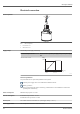
Table Of Contents
- Table of contents
- Important document information
- Terms and abbreviations
- Registered trademarks
- Product life cycle
- Measuring principle
- Input
- Output
- Electrical connection
- Performance characteristics
- Installation
- Environment
- Process
- Mechanical construction
- Operability
- Certificates and approvals
- Ordering information
- Accessories
- Supplementary documentation

Micropilot FMR10
8 Endress+Hauser
Input
Measured variable
The measured variable is the distance between the reference point and the product surface.
The level is calculated based on E, the empty distance entered.
Measuring range Maximum measuring range
Device Maximum measuring range
FMR10 5 m (16 ft)
FMR10 with accessory "flooding protection tube" 8 m (26.25 ft)
Requirements of the installation
• Tank height > 1.5 m (5 ft)
• Open channel minimum width 0.5 m (1.6 ft)
• Calm surfaces
• No agitators
• No buildup
• Relative dielectric constant ε
r
> 4
Usable measuring range
The usable measuring range depends on the antenna size, the medium's reflective properties, the
installation position and any possible interference reflections.
The following table describes the media groups.
Media groups
ε
r
Example
4 to 10 e.g. concentrated acid, organic solvents, ester, aniline, alcohol, acetone.
> 10 conductive liquids, aqueous solutions, diluted acids and bases
Reduction of the max. possible measuring range by:
• Media with bad reflective properties (= low ε
r
value)
• Formation of buildup, particularly of moist products
• Strong condensation
• Foam generation
• Freezing of sensor
Operating frequency
K-band (~ 26 GHz)
Transmission power
Distance Mean power density in the direction of the beam
1 m (3.3 ft) < 12 nW/cm
2
5 m (16 ft) < 0.4 nW/cm
2