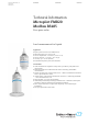
TI01437F/00/EN/01.18 71426193 2018-12-07 Products Solutions Services Technical Information Micropilot FMR20 Modbus RS485 Free space radar Level measurement for liquids Application • • • • • • Ingress protection: IP66/68 / NEMA 4X/6P Measuring range: up to 20 m (66 ft) Process temperature: –40 to 80 °C (–40 to 176 °F) Process pressure: –1 to 3 bar (–14 to 43 psi) Accuracy: up to ± 2 mm (0.
Micropilot FMR20 Modbus RS485 Table of contents Important document information . . . . . . . . . . . . . . . 3 Symbols used . . . . . . . . . . . . . . . . . . . . . . . . . . . . . . . . 3 Terms and abbreviations . . . . . . . . . . . . . . . . . . . . . 4 Registered trademarks . . . . . . . . . . . . . . . . . . . . . . . 4 Product life cycle . . . . . . . . . . . . . . . . . . . . . . . . . . . . 5 Engineering . . . . . . . . . . . . . . . . . . . . . . . . . . . . . . . . . Procurement . . . . . .
Micropilot FMR20 Modbus RS485 Important document information Symbols used Safety symbols DANGER This symbol alerts you to a dangerous situation. Failure to avoid this situation will result in serious or fatal injury. WARNING This symbol alerts you to a dangerous situation. Failure to avoid this situation can result in serious or fatal injury. CAUTION This symbol alerts you to a dangerous situation. Failure to avoid this situation can result in minor or medium injury.
Micropilot FMR20 Modbus RS485 Terms and abbreviations BA Document type "Operating Instructions" KA Document type "Brief Operating Instructions" TI Document type "Technical Information" SD Document type "Special Documentation" XA Document type "Safety Instructions" PN Nominal pressure MWP MWP (Maximum working pressure/max. process pressure) The MWP can also be found on the nameplate.
Micropilot FMR20 Modbus RS485 Product life cycle Engineering • • • • • • • • Proven radar measuring technology Level measurement and open channel flow measurement for Ex and non-Ex areas Flooding detection Wide range of installation possibilities and accessories Highest degree of ingress protection 2D/3D drawings Spec Sheet Producer Applicator Selection tool for selecting the perfect measurement solution Device not compatible with transmitters and sensors that use ultrasonic measurement technology (e.g.
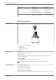
Micropilot FMR20 Modbus RS485 Measuring principle The Micropilot is a "downward-looking" measuring system, which functions according to the time-offlight (ToF) method. It measures the distance from the reference point R to the product surface. Radar pulses are emitted by an antenna, reflected off the product surface and received again by the radar system.
Micropilot FMR20 Modbus RS485 Input Measured variable The measured variable is the distance between the reference point and the product surface. The level is calculated based on E, the empty distance entered. Measuring range Maximum measuring range • Device with 40 mm (1.5 in) antenna: 10 m (33 ft) • Device with 80 mm (3 in) antenna: 20 m (66 ft) Installation requirements • • • • • • Recommended tank height > 1.5 m (5 ft) for media with low εr value Open channel minimum width 0.5 m (1.
Micropilot FMR20 Modbus RS485 Signal on alarm Depending on the interface, failure information is displayed as follows: • Digital communication (Modbus) – Status signal (as per NAMUR Recommendation NE 107) – Diagnostic code • Operating tool via SmartBlue (app) – Status signal (as per NAMUR Recommendation NE 107) – Plain text display with remedial action Linearization The linearization function of the device allows the conversion of the measured value into any unit of length, weight, flow or volume.
Micropilot FMR20 Modbus RS485 Modbus address Parameter name Description 5006 MODB_QV_VALUE Temperature (QV) 5008 MODB_SIGNALQUALITY Signal quality 5010 MODB_ACTUALDIAGNOSTICS Current diagnostics number 5012 MODB_LOCATION_LONGITUDE Longitude coordinate 5014 MODB_LOCATION_LATITUDE Latitude coordinate Electrical connection Cable assignment 2 1 + D0 / A (+) D1 / B (-) 3 4 A0037750 2 1 2 3 4 Supply voltage FMR20 cable assignment, Modbus Plus, brown wire Minus, blue wire Modbus D0/A (+)
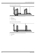
Micropilot FMR20 Modbus RS485 Single shot mode switched on/off via RTU P(mW) 39 33 B B A A 30 C 8 C 3 D E t(s) A0038152 3 A B C D E Power consumption of single shot mode switched on/off via RTU Start-up Measurement Power save mode Switch on power supply Switch off power supply Single shot mode switched on permanently P(mW) 39 B 30 B C 3 C F t(s) A0038151 4 B C F 10 Power consumption of single shot mode switched on permanently Measurement Power save mode Trigger Endress+Hauser
Micropilot FMR20 Modbus RS485 Continuous measuring mode switched on/off via RTU P(mW) 39 33 B BBBBBBBB B BBBBBBBB A A 8 3 1 C D t(s) A0038153 5 A B C D Power consumption of continuous measuring mode switched on/off via RTU Start-up Measurement Switch on power supply Switch off power supply Calculation example Assumed configuration • RTU: E+H FXA30B with battery (7.2 V, 14.
Micropilot FMR20 Modbus RS485 1 - DO / A(+) + D1 / B(-) - + + 2 3 A0037751 6 1 2 3 Block circuit diagram for Modbus RS485 connection Device with Modbus communication Modbus master/RTU Power supply Up to 32 users can be connected on the RS485 bus.
Micropilot FMR20 Modbus RS485 Cable specification Unshielded cable, wire cross-section 0.22 mm2 • UV- and weather-resistant • Flame resistance according to IEC 60332-1-2 As per IEC/EN 60079-11 section 10.9, the cable is designed for a tensile strength of 30 N (6.74 lbf) (over a period of 1 h). The device is supplied with 5 m (16 ft) cable length as standard. Cable lengths 10 m (33 ft) and 20 m (66 ft) are optionally available.
Micropilot FMR20 Modbus RS485 Response time The response time can be configured. The following step response times apply (in accordance with DIN EN 61298-2) when damping is switched off: Tank height <20 m (66 ft) Sampling rate 1 s-1 Response time <3 s In accordance with DIN EN 61298-2, the step response time is the time following an abrupt change in the input signal up until the changed output signal has adopted 90% of the steadystate value for the first time.
Micropilot FMR20 Modbus RS485 Position for installation on a tank BD A D A0028410 11 Installation position on a tank • If possible install the sensor so that its lower edge projects into the tank. • Recommended distance A wall - nozzle outer edge: ~ ¹⁄₆ of the tank diameter D. Under no circumstances should the device be mounted closer than 15 cm (5.91 in) to the tank wall. • Do not install the sensor in the middle of the tank. • Avoid measurements through the filling curtain.
Micropilot FMR20 Modbus RS485 The maximum length of the nozzle L depends on the nozzle diameter D. Please note the limits for the diameter and length of the nozzle. 80 mm (3 in) antenna, installation inside nozzle • D: min. 120 mm (4.72 in) • L: max. 205 mm (8.07 in) + D × 4.5 80 mm (3 in) antenna, installation outside nozzle • D: min. 80 mm (3 in) • L: max. D × 4.5 40 mm (1.5 in) antenna, installation outside nozzle • D: min. 40 mm (1.5 in) • L: max. D × 1.5 40 mm (1.
Micropilot FMR20 Modbus RS485 The beam angle is defined as the angle α, at which the power density of the radar waves reaches half the value of the maximum power density (3 dB width). Microwaves are also emitted outside the signal beam and can be reflected off interfering installations. Beam diameter W as a function of beam angle α and distance D. 40 mm (1.5 in) antenna, α 30 ° W = D × 0.54 40 mm (1.5 in) antenna with flooding protection tube, α 12 ° W = D × 0.
Micropilot FMR20 Modbus RS485 A0031277 16 Protective hood, e.g. with 40 mm (1.5") antenna The sensor is not completely covered by the protective hood. Free-field measurement with flooding protection tube The flooding protection tube ensures the sensor measures the maximum level even if it is completely flooded. In free-field installations and/or in applications where there is a risk of flooding, the flooding protection tube must be used.
Micropilot FMR20 Modbus RS485 Installation with mounting bracket, adjustable The mounting bracket can be ordered as an accessory or together with the device via the product structure "Accessory enclosed". A0030606 18 Installation with mounting bracket, adjustable • Wall or ceiling installation is possible. • Using the mounting bracket, position the antenna so that it is perpendicular to the product surface. NOTICE There is no conductive connection between the mounting bracket and transmitter housing.
Micropilot FMR20 Modbus RS485 A0037747 20 Horizontal installation with reflector plate Mounting in a shaft The pivoted mounting bracket is available as an accessory. A B A0037748 21 A B Mounting in a shaft, pivotable and adjustable Arm with wall bracket Pivotable and adjustable arm (e.g.
Micropilot FMR20 Modbus RS485 Process Process temperature, process pressure p [bar (psi)] 3 (43.5) 0 -1(-14.5) Tp -40 0 (+32) +80 (+176) [°C (°F)] A0029007-EN 22 FMR20: Permitted range for process temperature and process pressure Process temperature range –40 to +80 °C (–40 to +176 °F) Process pressure range, threaded process connection • prel = –1 to 3 bar (–14.5 to 43.5 psi) • pabs < 4 bar (58 psi) Process pressure range, UNI flange process connection • prel = –1 to 1 bar (–14.5 to 14.
Micropilot FMR20 Modbus RS485 Mechanical construction Dimensions 40 mm (1.5 in) Antenna with G 1-½" or MNPT 1-½" thread ø75 (2.95) 26 (1.02) B 20 (0.79) 28 (1.1) 112 (4.4) 140 (5.5) A G 1" NPT 1" G 1 1/2" NPT 1 1/2" A0028805 23 A B Dimensions of G 1-½" or MNPT 1-½" process connection thread, engineering unit: mm (in) Cable gland FNPT ½“ conduit 40 mm (1.5 in) Antenna with G 2" or MNPT 2" thread ø75 (2.95) B 26 (1.02) 20 (0.79) 28 (1.1) 112 (4.4) 140 (5.
Micropilot FMR20 Modbus RS485 40 mm (1.5 in) antenna with flooding protection tube 264 (10.4) !75 (2.95) !89 (3.5) A0030266 25 Dimensions of 40 mm (1.5 in) antenna mounted with flooding protection tube, engineering unit: mm (in) The flooding protection tube, metalized PBT-PC, can be ordered together with the device via the product structure "Accessory enclosed". 80 mm (3 in)Antenna ø75 (2.95) 20 (0.79) 26 (1.02) B G 1" NPT 1" 9 (0.35) 206 (8.11) 28 (1.1) A ø115 (4.
Micropilot FMR20 Modbus RS485 80 mm (3 in) antenna with flooding protection tube ø75 (2.95) 20 (0.79) 26 (1.02) B G 1" NPT 1" 317 (12.5) 28 (1.1) A !98,2 (3.87) !138,1 (5.44) A0031095 27 A B Dimensions of 80 mm (3 in) antenna mounted with flooding protection tube, engineering unit: mm (in) Cable gland FNPT ½“ conduit The flooding protection tube, metalized PBT-PC, can be ordered together with the device via the product structure "Accessory enclosed".
Micropilot FMR20 Modbus RS485 178 (7) 80 mm (3 in) antenna with slip-on flange 3"/DN80 ø75 (2.95) ø115.6 (4.55) ø156.2 (6.15) ø200 (7.87) 9 (0.36) 18.5 (0.73) 8x ø21 (0.83) A0028813 28 Dimensions of 80 mm (3 in) antenna with slip-on flange 3"/DN80, engineering unit: mm (in) The slip-on flange 3"/DN80, PVDF, can be ordered together with the device via the product structure "Accessory enclosed". 80 mm (3 in) antenna with slip-on flange 4"/DN100 30.5 (1.2) 20 (0.79) 188 (7.4) 8x 19 (0.
Micropilot FMR20 Modbus RS485 80 mm (3 in) antenna with slip-on flange 6"/DN150 30.5 (1.2) 20 (0.79) 188 (7.4) 8x 23 (0.91) ø143 (5.63) ø98 (3.86) ø240 (9.45) ø241.3 (9.5) ø285 (11.2) A0028818 30 Dimensions of 80 mm (3 in) antenna with slip-on flange 6"/DN150, engineering unit: mm (in) The slip-on flange 6"/DN150, PVDF, can be ordered together with the device via the product structure "Accessory enclosed". G 1" 8 (0.31) 1 2 (0.08) 2 (0.
Micropilot FMR20 Modbus RS485 Materials B A 4 5 6 7 3 2 4 5 6 7 3 2 1 1 8 8 9 9 A0028416 32 A B 1 2 3 4 5 6 7 8 9 Connecting cable Overview of materials 40 mm (1.5 in)Antenna 80 mm (3 in)Antenna Sensor housing; PVDF Seal; EPDM Process connection, rear side; PVDF Cable gland; PA Conduit adapter; CuZn nickel-plated O-ring; EPDM Counter nut; PA6.
Micropilot FMR20 Modbus RS485 Remote operation via Modbus protocol 2 4 3 5 1 7 6 A0037752 34 1 2 3 4 5 6 7 28 Options for remote operation via Modbus protocol Computer with Modbus operating tool (client application, terminal application, etc.) Remote Transmit Unit (RTU) with Modbus (e.g.
Micropilot FMR20 Modbus RS485 Certificates and approvals The availability of approvals and certificates can be called up daily via the Product Configurator. CE mark The measuring system meets the legal requirements of the applicable EC guidelines. These are listed in the corresponding EC Declaration of Conformity together with the standards applied. Endress+Hauser confirms successful testing of the device by affixing to it the CE mark.
Micropilot FMR20 Modbus RS485 Please note the following for operation of the devices outside of closed vessels: 1. The device must be mounted in accordance with the instructions in the "Installation" section. 2. Installation must be carried out by properly trained, expert staff. 3. The device antenna must be installed in a fixed location pointing vertically downwards. 4.
Micropilot FMR20 Modbus RS485 [Any] Changes or modifications made to this equipment not expressly approved by Endress+Hauser may void the FCC authorization to operate this equipment. This equipment has been tested and found to comply with the limits for a Class B digital device, pursuant to Part 15 of the FCC Rules. These limits are designed to provide reasonable protection against harmful interference in a residential installation.
Micropilot FMR20 Modbus RS485 • NAMUR NE 107 Status classification as per NE107 • NAMUR NE 131 Requirements for field devices for standard applications • IEEE 802.15.1 Requirements for the Bluetooth® wireless technology interface Ordering information Detailed ordering information is available from the following sources: • In the Product Configurator on the Endress+Hauser website: www.endress.
90 (3.54) 90 (3.54) Micropilot FMR20 Modbus RS485 Ø 98 (3.86) Ø 98 (3.86) A0028841 35 Dimensions of protective cover, engineering unit: mm (in) Material PVDF Order number 52025686 The sensor is not completely covered in the case of the 40 mm (1.5 in) antenna or the 80 mm (3 in) antenna. Securing nut G 1-1/2" 10 (0.39) Suitable for devices with G 1-1/2" and MNPT 1-1/2" process connection.
Micropilot FMR20 Modbus RS485 Order number 52014146 Securing nut G 2" G 2" 10 (0.39) Suitable for devices with G 2" and MNPT 2" process connection on front.
Micropilot FMR20 Modbus RS485 Flooding protection tube 40 mm (1.5 in) Suitable for use with devices with a 40 mm (1.5 in) antenna and G 1-1/2" process connection on front. The flooding protection tube can be ordered together with the device via the product structure "Accessory enclosed". 152 (5,98) G 1-1/2" !89 (3,5) A0028418 38 Dimensions of 40 mm (1.
Micropilot FMR20 Modbus RS485 Flooding protection tube 80 mm (3 in) Suitable for use with devices with a 80 mm (3 in) antenna and "Mounting customer side w/o flange" process connection. The flooding protection tube can be ordered together with the device via the product structure "Accessory enclosed". 136,5 (5.37) !138 (5.43) !97,3 (3.
Micropilot FMR20 Modbus RS485 Mounting bracket, adjustable The mounting bracket can be ordered together with the device via the product structure "Accessory enclosed". 92.5 (3.64) 12 (0.47) 12 (0.47) 9 (0.35) 35 (1.38) 117.5 (4.63) 70 (2.76) !9 (0.35) 9 (0.35) A0028861 40 Dimensions of mounting bracket, engineering unit: mm (in) Consists of: • 1 × mounting bracket, 316L (1.4404) • 1 × mounting bracket, 316L (1.
Micropilot FMR20 Modbus RS485 UNI flange 2"/DN50/50, PP The UNI flange 2"/DN50/50 can be ordered together with the device via the product structure "Accessory enclosed". 90 °( =3 60 °) 20 (0.79) 19 (0.75) 4× A 120 (4.72) 125 (4.92) 165 (6.
Micropilot FMR20 Modbus RS485 UNI flange 3"/DN80/80, PP 20 (0.79) 19 (0.75) The UNI flange 3"/DN80/80 can be ordered together with the device via the product structure "Accessory enclosed". A 150 (5.91) 160 (6.3) 200 (7.
Micropilot FMR20 Modbus RS485 UNI flange 4"/DN100/100, PP 20 (0.79) 19 (0.75) The UNI flange 4"/DN100/100 can be ordered together with the device via the product structure "Accessory enclosed". A 175 (6.89) 190.5 (7.5) 228.6 (9.
Micropilot FMR20 Modbus RS485 Angle bracket for wall mounting 400 (15.7) 3 (0.12) 120 (4.72) ø16 (0.6) 30 (1.2) 250 (9.84) G 120 (4.72) A0019346 44 G Dimensions of angle bracket, engineering unit: mm (in) Sensor connection in accordance with product structure "Process connection on front" Weight 3.4 kg (7.5 lb) Material 316 Ti (1.
Micropilot FMR20 Modbus RS485 Cantilever with pivot Installation type sensor process connection rear side A B 1 1 3 2 A0028885 45 A B 1 2 3 Installation type sensor process connection rear side Installation with cantilever and wall bracket Installation with cantilever and mounting frame Cantilever Wall bracket Mounting frame 20 (0.8) 2 (0.08) 20 (0.8) 585 (23) 35 (1.4) 200 (7.87) M8 250 (9.84) 35 (1.4) 15 (0.6) 6.5 (0.3) 2 (0.08) 22 (0.9) 35 (1.4) 105 (4.1) 75 (2.9)75 (2.9)100 (3.
Micropilot FMR20 Modbus RS485 20 (0.8) 3 (0.12) 20 (0.8) 1085 (42.7) 35 (1.4) 300 (11.8) M8 750 (29.5) 35 (1.4) 15 (0.6) 6.5 (0.3) 3 (0.12) 22 (0.9) 35 (1.4) 105 (4.1) 75 (2.9)75 (2.9)100 (3.9) 50 25 (1.0) 100 (3.9) (2.0) Cantilever (long) with pivot, sensor process connection on rear A0037807 47 Dimensions of cantilever (long) with pivot for sensor process connection on rear, engineering unit: mm (in) Weight: 4.5 kg (9.
Micropilot FMR20 Modbus RS485 20 (0.8) 2 (0.08) 20 (0.8) 585 (23) 35 (1.4) 200 (7.87) 250 (9.84) 35 (1.4) 15 (0.6) 6.5 (0.3) 2 (0.08) 22 (0.9) 50 (2.0) 105 (4.1) 75 (2.9)75 (2.9)100 (3.9) M8 25 (1.0) 50 (2.0) 100 (3.9) Cantilever (short) with pivot, G 1-½" sensor process connection on front A0037802 49 Dimensions of cantilever (short) with pivot for G 1-½" sensor process connection on front, engineering unit: mm (in) Weight: 1.9 kg (4.
Micropilot FMR20 Modbus RS485 Weight: 4.4 kg (9.7 lb) Material: Steel, hot-dip galvanized Order number: 52014133 Material: Steel, 316Ti (1.4571) Order number: 52014134 • 50 mm (2.17 in) openings for all G 1-½" (MNPT 1-½") connections on front • 22 mm (0.87 in) opening can be used for an additional sensor • Retaining screws are included in delivery 20 (0.8) 2 (0.08) 20 (0.8) 585 (23) 35 (1.4) 200 (7.87) 250 (9.84) 35 (1.4) 15 (0.6) 6.5 (0.3) 2 (0.08) 22 (0.9) 62 (2.4) 105 (4.1) 75 (2.9)75 (2.
Micropilot FMR20 Modbus RS485 20 (0.8) 3 (0.12) 20 (0.8) 1085 (42.7) 35 (1.4) 300 (11.8) 750 (29.5) 35 (1.4) 15 (0.6) 6.5 (0.3) 3 (0.12) 62 (2.4) 22 (0.9) 105 (4.1) 75 (2.9)75 (2.9)100 (3.9) M8 25 (1.0) 50 (2.0) 100 (3.9) Cantilever (long) with pivot, G 2" sensor process connection on front A0037805 52 Dimensions of cantilever (long) with pivot for G 1-½" sensor process connection on front, engineering unit: mm (in) Weight: 4.4 kg (9.
Micropilot FMR20 Modbus RS485 Weight: 3.2 kg (7.06 lb) Material: Steel, hot-dip galvanized Order number: 919791-0000 Material: Steel, 316Ti (1.4571) Order number: 919791-0001 Mounting frame (long) for cantilever with pivot 3.2 (0.13) 60 (2.36) 1400 (55.1) ø33.7 (1.3) 25 (0.98) 75 (2.95) 55 (2.17) 109 (4.29) 100 76 (3.94) (2.99) 200 (7.87) 4 (0.16) 6.5 (0.3) 45 (1.77) 13 (0.5) 100 (3.94) 20 (0.8) 100 (3.94) 130 (5.12) 150 (5.
Micropilot FMR20 Modbus RS485 Weight 1.4 kg (3.09 lb) Order number: Steel, galvanized 919792-0000 Order number: 316Ti (1.
Micropilot FMR20 Modbus RS485 Ceiling mounting bracket The ceiling mounting bracket can be ordered together with the device via the product structure "Accessory enclosed". 75 1.5 185 105 12 ø5.6 110±2 15 50 95 100 10 10 10 5 ø35 15 155 A0028891 56 Dimensions of ceiling mounting bracket, engineering unit: mm (in) Material 316L (1.
Micropilot FMR20 Modbus RS485 Pivoted mounting bracket for sewer channel The pivotable mounting bracket is used to install the device in a manhole over a sewer channel. The mounting bracket can be ordered together with the device via the "Enclosed accessories" section of the product order structure. 6.8 (0.27) 110 (4.33) 100 (3.94) 6.8 (0.27) 360 (14.2) A0038143 57 Dimensions of the pivotable mounting bracket, engineering unit: mm (in) Material 316L (1.4404) Order number t.b.d.
Micropilot FMR20 Modbus RS485 Reflector plate for horizontal mounting The reflector plate is used for installation in confined spaces (sewer shafts). The reflector plate can be ordered together with the device via the "Enclosed accessories" section of the product order structure. 144 (5.67) 100 (3.94) 280 (11) 100 (3.94) !9 (0.35) A0038142 58 Dimensions of reflector plate, engineering unit: mm (in) Material 316L (1.4404) Order number t.b.d.
*71426193* 71426193 www.addresses.endress.