
Installation Instructions
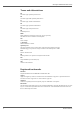
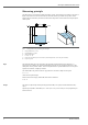
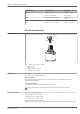
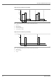
Table Of Contents
- Table of contents
- Important document information
- Terms and abbreviations
- Registered trademarks
- Product life cycle
- Measuring principle
- Input
- Output
- Protocol-specific data, Modbus
- Electrical connection
- Performance characteristics
- Installation
- Environment
- Process
- Mechanical construction
- Operability
- Certificates and approvals
- Ordering information
- Accessories
- Documentation

Micropilot FMR20 Modbus RS485
6 Endress+Hauser
Measuring principle
The Micropilot is a "downward-looking" measuring system, which functions according to the time-of-
flight (ToF) method. It measures the distance from the reference point R to the product surface.
Radar pulses are emitted by an antenna, reflected off the product surface and received again by the
radar system.
D
Q
R
100%
0%
D
L
F
E
A0028409
1 Setup parameters of the Micropilot Micropilot
E Empty calibration (= zero)
F Full calibration (= span)
D Measured distance
L Level (L = E - D)
Q Flow rate at measuring weirs or channels (calculated from the level using linearization)
R Reference point
Input
The reflected radar pulses are received by the antenna and transmitted to the electronics. A
microprocessor evaluates the signals and identifies the level echo caused by the reflection of the
radar pulses at the product surface. This clear signal detection system benefits from over 30 years'
experience with time-of-flight procedures.
The distance D to the product surface is proportional to the time of flight t of the pulse:
D = c · t/2,
where c is the speed of light.
Based on the known empty distance E, the level L is calculated:
L = E – D
Output
The device is adjusted by entering the empty distance E (= zero point) and the full distance F (=
span).
Digital output (Modbus, SmartBlue): 0 to 10 m (0 to 33 ft) or 0 to 20 m (0 to 66 ft) depending on
antenna version