
Product Info


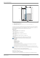
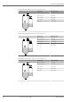
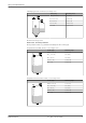

Table Of Contents
- Table of contents
- Important document information
- Function and system design
- Input
- Output
- Power supply
- Performance characteristics
- Mounting
- Environment
- Process
- Mechanical construction
- Operability
- Certificates and approvals
- Ordering information
- Application packages
- Accessories
- Weather protection cover 316L
- Plastic weather protection cover
- Mounting bracket, adjustable
- M12 socket
- Remote display FHX50B
- Gas-tight feedthrough
- Commubox FXA195 HART
- HART Loop Converter HMX50
- FieldPort SWA50
- Wireless HART adapter SWA70
- Fieldgate FXA42
- Field Xpert SMT70
- DeviceCare SFE100
- FieldCare SFE500
- Memograph M
- RN42
- Documentation
- Registered trademarks

Micropilot FMR60B HART
Endress+Hauser V. 1, Rev. 2, 26-07-2022 5
Graphic conventions
• Installation, explosion and electrical connection drawings are presented in simplified format
• Devices, assemblies, components and dimensional drawings are presented in reduced-line
format
• Dimensional drawings are not to-scale representations; the dimensions indicated are
rounded off to 2 decimal places
• Unless otherwise described, flanges are presented with sealing surface form EN1091-1, B2;
ASME B16.5, RF; JIS B2220, RF
Function and system design
Measuring principle
The Micropilot is a "downward-looking" measuring system, operating based on the frequency
modulated continuous wave method (FMCW). The antenna emits an electromagnetic wave at a
continuously varying frequency. This wave is reflected by the product and received again by the
antenna.
D
R
A0032017
1 FMCW principle: transmission and reflection of the continuous wave
R Reference point of measurement
D Distance between reference point and product surface
The frequency of this wave is modulated in the form of a sawtooth signal between two limit
frequencies f
1
and f
2
:
f
t
1
2
f
2
f
1
∆t
∆f
A0023771
2 FMCW principle: result of frequency modulation
1 Transmitted signal
2 Received signal
This results in the following difference frequency at any time between the transmitted signal and the
received signal:
∆f = k ∆t
where ∆t is the run time and k is the specified increase in frequency modulation.
∆t is given by the distance D between the reference point R and the product surface: