
Installation Instructions

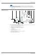
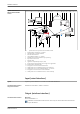
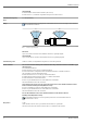
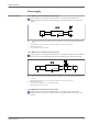
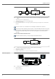
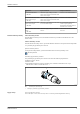
Table Of Contents
- Table of contents
- About this document
- Function and system design
- Input (wired interface)
- Output (wireless interface)
- Power supply
- Installation
- Environment
- Mechanical construction
- Human interface
- Certificates and approvals
- Ordering information
- Accessories
- Supplementary documentation
- Registered trademarks
- Radio approvals

FieldPort SWA50
Endress+Hauser 9
Application Input terminal IN Output terminal OUT
2-wire HART field device
→ 4, 7
Cable from supply voltage, PLC with
active current output or transmitter with
active current output
Cable to 2-wire HART field device
4-wire HART field device with
passive current output
→ 5, 7
Cable from supply voltage, PLC with
active current output or transmitter with
active current output
Cable to 4-wire HART field device
4-wire HART field device with
active current output
→ 6, 8
Cable from 4-wire field device with active
4 to 20 mA HART output
PLC or transmitter with passive
current output (optional),
alternatively wire bridge between
terminals OUT+ and OUT–
FieldPort SWA50 without field
device
→ 7, 8
Cable from supply voltage for FieldPort
SWA50
Resistor between terminals OUT+
and OUT–
FieldPort SWA50 grounding "Direct mounting" version
With the "direct mounting" version, the FieldPort SWA50 is grounded via the field device or the
metal conduit.
"Remote mounting" version
With the "remote mounting" version, ground the FieldPort SWA50 via the optional mounting bracket
or a grounding clip provided by the customer.
Optional mounting bracket
If using the mounting bracket, ground the FieldPort SWA50 via the grounding screw.
Mounting bracket
Grounding clip provided by customer
The grounding clip provided by the customer must meet the following requirements:
• Diameter: approx. 40 mm
• Stainless steel
• If the FieldPort SWA50 is used in a hazardous area: suitable for hazardous areas as per
DIN EN 62305, Sheet 3 and DIN EN 62561-1
1
A0041808
9 Grounding via grounding clip
1 Example of grounding clip provided by customer
Supply voltage
• Loop-powered 4 to 20 mA
• 24 V DC (min. 4 V DC, max. 30 V DC): min. 3.6 mA loop current required for start-up