
User's Manual


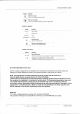


Table Of Contents

DRAFT
Micropilot FMR56, FMR57
Endress+Hauser V. 1, Rev. 6, 19-10-2012 5
Function and system design
Measuring principle
The Micropilot is a "downward-looking" measuring system, operating based on the time-of-flight method
(ToF). It measures the distance from the reference point (process connection) to the product surface. Radar
impulses are emitted by an antenna, reflected off the product surface and received again by the radar system.
F
L
D
E
100%
0%
R
A0017872
å 1
Setup parameters of the Micropilot
R
Reference point of the measurement (lower edge of the flange or threaded connection)
E Empty calibration ( = zero)
F Full calibration (= span)
D Measured distance
L Level (L = E - D)
Input
The reflected radar impulses are received by the antenna and transmitted into the electronics. A
microprocessor evaluates the signal and identifies the level echo caused by the reflection of the radar impulse
at the product surface. The unambiguous signal identification is accomplished by the PulseMaster® eXact
software together with the Multi-echo tracking algorithms, based on many years of experience with time-of-
flight technology.
The distance D to the product surface is proportional to the time of flight t of the impulse:
D = c · t/2,
with c being the speed of light.
Based on the known empty distance E, the level L is calculated:
L = E – D
The reference point R of the measurement is located at the process connection. For details see the
dimensional drawing:
•
FMR56: (® ä 55)
•
FMR57: (® ä 58)
The Micropilot is equipped with functions to suppress interference echoes. The user can activate these
functions. Together with the multi-echo tracking algorithms they ensure that interference echoes (i.e. from
edges and weld seams) are not interpreted as level echo.