
Product Manual


Page 1
Installation Instructions
Windlass Model WCH800
Horizontal Mount
CONTENTS IN PACKAGE
WCH800 WINDLASS
Circuit breaker assembly with bracket, nut, and bolt
12 volt DC solenoid 100amp
Deck foot switch package
REQUIRED TO PURCHASE
1. 4-5/16” (8mm) stainless steel flat head bolts.
(length to be determined by deck thickness).
2. 4-5/16” (8mm) nuts and washers.
3. 18 ga insulated wire, length as required between the
solenoid and deck foot switch.
4. 1-1/4” hole saw.
5. 8 ga insulated wire if run from battery 20ft or less.
6. 6 ga insulated wire if run from battery over 20ft.
INSTRUCTIONS
1. Select the proper position on deck for the Windlass. Make
sure that this area of the deck is strong enough to
withstand windlass loads and have adequate access to
retrieve the anchor line or boat. Reinforce the deck with a
backing plate if necessary.
2. Use the windlass base holes to make the 4 mounting
bolts. Drill 4-3/8” (10mm) holes
through the deck.
3. Drill a 3/8” (10mm) hole through the
windlass base hole for the 6-8 ga
wires.
4. With sealant, bolt the windlass to the
deck with the 5/16” bolts and washers.
Run the wires through the windlass
base and deck and seal the hole.
5. Select a location for the foot-activated
deck switch where you can activate
the windlass while handling the line.
Use the 1-1/4” hole saw to drill
through the deck. The assembled
switch with wiring will fit in this hole.
Adjust the height of the switch in the
bottom switch plate with the inner nut (as noted in
Diagram A, lock the bottom nut, and connect the two 18
ga wires to the terminals. With sealant, mount the foot
switch assembly on the deck with the screws purchased.
As you probably know, a capstan
is a very flexible piece of hauling
gear since the strength with
which it pulls is proportional to
the light pull you apply to the tail
end of the line. The more coils on
the capstan drum, the greater the
friction and the lower the pull
required by the operator.
The motor unit develops nearly
one horsepower and is designed
for intermittent, not continuous
duty. After using the windlass for
a period, let it cool down as much
as possible before again
stressing it.
This way you will be assured for
a long operation life
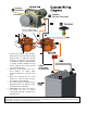
Retainer ring
Rubber Switch Cover
Insert
Base Plate
Switch
Adjust this nut so
the top of the switch
just touches the insert
when the rubber switch
is mounted on the base
plate.
Mount the retainer ring and
assembly to the floor with
the screws provided.
Tighten this lock nut after the
switch is positioned in the base
plate.
Assembly mounts
into a 1-1/4” hole
in the floor
Diagram A: Foot Switch Mounting
Wires to the solenoid terminals
Endurance Marine Products Ltd
Surrey, British Columbia, Canada, V3S 3V7
Phone Toll Free 877.535.0669
Phone 604.535.0669 Fax 604.535.0681