Operating Instructions Digital Video Recorder H.
Digital Video Recorder Safety instructions EMC class ► This video recorder (DVR) is a class A device in accordance with EN 55022. ► This device may cause interference to other equipment in domestic use. In such cases the persons operating the DVR are required to provide appropriate countermeasures, for which they themselves bear the cost.
Operating Instructions Table of Contents Chapter 1 — Introduction ......................................................................................................... 1 Feature ................................................................................................................................1 Technical Overview..............................................................................................................1 Chapter 2 — Installation.............................................
Digital Video Recorder Date/Time ....................................................................................................13 Storage........................................................................................................14 User ............................................................................................................15 Shutdown .....................................................................................................17 Network Setup ..................
Operating Instructions Text-In Search ..............................................................................................55 Clip-Copy .....................................................................................................56 Print ............................................................................................................57 Appendix ................................................................................................................................
Digital Video Recorder Figure 21 — WebGuard setup screen. ....................................................................................................20 Figure 22 — Notification Mail setup screen..............................................................................................20 Figure 23 — Notification Callback setup screen. .....................................................................................21 Figure 24 — Devices menu...................................................
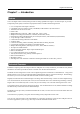
Digital Video Recorder Chapter 1 — Introduction Feature Your color digital video recorder (DVR) provides recording capabilities for eight or 16 camera inputs. It provides exceptional picture quality in both live and playback modes, and offers the following features: y y y y y y y y y y y y y y y y y y y y y 8 or 16 Composite Video Input Connectors Compatible with Color (NTSC or PAL) and B&W (CCIR and EIA-170) Video Sources Auto Detection for NTSC and PAL H.
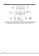
Operating Instructions Figure 1 — Typical DVR installation. NOTE: This manual covers the 8- and 16-channel digital video recorders. The DVRs are identical except for the number of cameras and alarms that can be connected and the number of cameras that can be displayed. For simplicity, the illustrations and descriptions in this manual refer to the 16-camera model.
Digital Video Recorder Chapter 2 — Installation Package Contents The package contains the following: y y y y y y y Digital Video Recorder Power Cord Operating Instructions (This Document) RAS Software CD and Operating Instructions Rack-mount Kit Assembly Screws and Guide Rails for Adding Hard Disk Drives Infrared Remote Control Required Installation Tools No special tools are required to install the DVR. Refer to the installation manuals for the other items that make up part of your system.
Operating Instructions If you would like to connect your video source to another device, you can use the Loop BNC connectors. NOTE: The Loop BNC connectors are auto terminated. Do NOT connect a cable to the Loop BNC unless it is connected to a terminated device because it will cause poor quality video. RS485 Port The DVR can be controlled remotely by an external device or control system, such as a control keyboard, using RS485 half-duplex serial communications signals.
Digital Video Recorder Video Out A VGA connector is provided so that you can use a standard, multi-sync computer monitor as your main monitor. Use the cable supplied with your monitor to connect it to the DVR. Connect the main monitor to the Video Out connector. Connect the spot monitor to the SPOT connector as needed. NOTE: The VGA and Video Out (BNC) connectors may be connected to individual monitors for simultaneous operation.
Operating Instructions Chapter 3 — Configuration NOTE: Your DVR should be completely installed before proceeding. Refer to Chapter 2 — Installation. Front Panel Controls Figure 3 — 16-Channel DVR front panel.
Digital Video Recorder Figure 4 — Infrared remote control. NOTE: For simplicity, the button descriptions in this manual refer to the front panel buttons. Camera Buttons (1 to 16) Pressing the individual camera buttons will cause the selected camera to display full screen. Buttons 1 to 9 are also used to enter passwords.
Operating Instructions CAMEO/MENU Button Pressing and holding the CAMEO/MENU button for three seconds or longer enters the cameo mode. The yellow outline surrounding the video indicates the active cameo, and pressing the arrow buttons moves the active cameo. Pressing the desired camera button in the active cameo edits the cameo and displays the video of selected camera. Pressing the (Play/Pause) button exits the Active Cameo mode.
Digital Video Recorder button plays video backward at high speed. Pressing the button again toggles In the playback mode, pressing the and . The screen displays , and respectively. Pressing the the playback speed from , button plays video forward at high speed. Pressing the button again toggles the playback speed from , . The screen displays , and respectively. When in the pause mode, pressing the button and moves to the next image and pressing the button moves to the previous image.
Operating Instructions Turning on the Power Connecting the power cord to the DVR turns on the unit. The unit takes approximately 60 seconds to initialize. Initial Unit Setup Before using your DVR for the first time, you will want to establish the initial settings. This includes items such as time and date, display language, camera, remote control, record mode, network and password. Your DVR can be set up using various screens and dialog boxes. Throughout the screens you will see .
Digital Video Recorder Press the MENU button or move the mouse pointer to the top of the screen and then select Monitoring menu to enter the setup screen. (Setup) in the Live While setting up the DVR, there will be many opportunities to enter names and titles. When making these entries, a Virtual Keyboard will appear. Use the arrow keys to highlight the character you want in the name or title and press the button. That character appears in the title bar and the cursor moves to the next position.
Operating Instructions To upgrade the software, connect a USB device containing the upgrade package file to the DVR. Highlight Upgrade… and press the button. The Upgrade screen appears. The screen displays the upgrade package file names that are available. The “.rui” indicates that the file is for software upgrades and “.ofi” indicates that the file is for optical drive firmware upgrades. Select the desired file and press the button.
Digital Video Recorder Highlighting Clear All Data… and pressing the button will clear all video data. You will be asked to verify that you wish to clear all data before the DVR erases the video data. Clear All Data… will not clear the System Log. Date/Time Highlight Date/Time in the System menu and press the button. The Date/Time setup screen appears. button. Highlight the first box beside Date and press the The individual sections of the date will highlight.
Operating Instructions Highlight the box beside Automatic Sync. and press the button. This toggles between On and Off. Highlight the box beside Time Server and press the button. A virtual keyboard appears that you can use to enter the IP address or domain name of the time server. NOTE: You can use the domain name instead of IP address if you already set up the DNS Server when setting up the LAN. Highlight the box beside Interval and press the button.
Digital Video Recorder If you want to erase recorded data on the selected device, highlight Clear and press the button. You will be asked whether or not you want to delete the data. If you want to use a USB hard disk drive, highlight Use and press the button after connecting the device. Highlight Don’t Use and press the button if you want to stop using the device. NOTE: When disconnecting a USB hard disk drive from the DVR, highlight Don’t Use first and then disconnect the device.
Operating Instructions CAUTION: Write down the new password and save it in a secure place. If the password is forgotten, the unit must be reset using the Factory Reset Button and all data settings will be lost. Highlighting a User Name and pressing the button allows you to add or change the password assigned to that user. You can also change the group to which the user is assigned. The column can be used to delete a User Name or an entire Group. If the is grayed out, that Group or User cannot be deleted.
Digital Video Recorder Shutdown Highlight Shutdown in the System menu and press the whether or not you want to shut the system down. button. The Shutdown screen displays asking you to confirm After selecting Shutdown and pressing the you when it is safe to disconnect power. button, a screen will appear telling Figure 16 — Shutdown screen. Network Setup Figure 17 — Network menu. Network button. The Network setup screen displays.
Operating Instructions Highlight the LAN tab, and the LAN screen displays. Highlight the box beside Type and press the button. You can select the type of network configuration from: Manual, DHCP and ADSL (with PPPoE). Select the desired type and press the button. Selecting Manual from the Type allows you to set up LAN parameters manually. Change the numbers by highlighting them and using the Up and Down arrow buttons to increase or decrease the number.
Digital Video Recorder Selecting ADSL (with PPPoE) allows you to set up the ADSL network. Highlight the box beside ID and press the button. A virtual keyboard appears allowing you to enter the ID for ADSL connection. Highlight the box beside Password and press the button. A virtual keyboard appears allowing you to enter the password for ADSL connection. NOTE: Entering the ID and Password and highlighting OK reads the current IP address of the DVR configured by the ADSL network.
Operating Instructions Highlight the WebGuard tab, and the WebGuard screen displays. Highlight Use WebGuard Service and press the button to toggle between On and Off. See Appendix – WebGuard for detailed descriptions of the WebGuard service. Highlight the box beside Port and press the button. Set the port number used when accessing WebGuard by using the Up and Down arrow buttons to increase or decrease the numbers. Figure 21 — WebGuard setup screen.
Digital Video Recorder Highlight the Callback tab, and the Callback screen displays. Highlight LAN and press the button to toggle between On and Off. When LAN is turned On you can change the IP addresses. Highlight the IP Address box that you want to change and press the button. Use the arrow buttons to enter the IP address of the computer you want contacted during an event. You can enter up to five IP addresses.
Operating Instructions Highlight the PTZ tab, and the PTZ setup screen displays. NOTE: You will only be able to set up PTZ devices if the PTZ port is set to RS232 or RS485. Figure 26 — Camera PTZ setup screen. Highlight the box in the Product column for the PTZ camera you wish to configure and press the button. A list of PTZ devices appears. Select your camera from the list and press the button.
Digital Video Recorder Alarm-Out Screen Highlight Alarm-Out in the Devices menu and press the button. The Alarm-Out screen allows you to change the settings and establish a schedule for each alarm output from the DVR. Each alarm output can be given its own title by highlighting button. the box under the Title heading and pressing the A virtual keyboard appears allowing you to enter the title.
Operating Instructions Display Highlight Display in the Devices menu and press the information will be displayed on the monitor. button. The Display screen allows you to select what Highlighting an item and pressing the button toggles that item On and Off. When an item is On, there is a checkmark in the box beside it. The following items can be turned On or Off: Figure 29 — Display OSD screen. displays when the DVR can be y Remote Control – The icon controlled by the infrared remote control.
Digital Video Recorder You can define the screen layout in a variety of formats and set the DVR to sequence through the different screen layouts (pages) so that all the cameras will be displayed. You can also set up the DVR to display one camera or a group of cameras all the time while cycling through the remaining cameras in a “cameo” window.
Operating Instructions Highlighting Position and pressing the button allows you to adjust the screen position on the VGA monitor. Use the arrow buttons on the setup screen to move the VGA screen position in the direction you want. Selecting the default button at the center cancels the screen positioning operation and reloads the default position. Remote Control Highlight Remote Control in the Devices menu and press the button.
Digital Video Recorder Recording Setup Figure 34 — Record menu. Record Highlight Record in the Record menu and press the button. The Record setup screen appears. Highlighting Recycle and pressing the button toggles between On and Off. In the Recycle mode, the DVR records over the oldest video data once all available storage space has been used. When Recycle is turned off, the DVR stops recording once all available storage space has been used.
Operating Instructions CAUTION: When more than one disk is installed in the unit, the DVR records video on the disks sequentially based on time. And these sequentially recorded videos have the advantage that you can search recorded video easily even though a disk is removed from the unit. However, video recorded in the same time range might be saved on different disks by channel and by the type of recording mode.
Digital Video Recorder Highlighting Schedule On and pressing the button toggles between On and Off. In the Schedule On mode, the DVR records video based on the schedule established in the Schedule screen. When turning Schedule recording Off, you will be asked to confirm your decision, and displays at the top-left corner of each camera screen. Panic recording will function even when Schedule is turned off. displays during panic recording. Highlight the Schedule Mode box and press the button.
Operating Instructions Highlight Default… and press the button. The Default screen appears. Highlighting boxes under ips and pressing the button allows you to set the images per second for Time and Event recording. You can select from 1.00 to 30.00 ips (25.00 ips PAL). Highlighting boxes under Quality and pressing the button allows you to set the recorded image quality for Time and Event recording. You can select from: Very High, High, Standard and Low.
Digital Video Recorder Event Setup Figure 40 — Event menu. Alarm-In Highlight Alarm-In in the Event menu and press the button. The Alarm-In setup screen appears. The alarm terminal strip on the back of the DVR has inputs associated with each alarm. You can set up each input on the Alarm-In screen. You can turn each input On or Off by highlighting the alarm number and pressing the button. Each input can be given a title. Highlight the desired Title box and press the button.
Operating Instructions NOTE: For the Alarm-Out action, the alarm output and beep you select should be set to the Event mode in the Alarm-Out setup screen (Schedule tab). Highlight the desired box under the Notify heading, and press the button. The Alarm-In Notify menu appears. You can toggle the entire list On and Off by highlighting Notification and pressing the button. You can toggle the individual items On and Off by highlighting that item and pressing the button.
Digital Video Recorder The Motion Detection Zone screen is laid over the video for the selected camera. You can set up motion detection zones by selecting or clearing blocks. NOTE: You can set up motion zones one block at a time in groups of 8 or 16 individual block groups (8- and 16-channel DVR respectively). A block group is positioned within the image area using the Up and Down arrow buttons, and individual blocks within the block groups are selected or cleared using the camera buttons.
Operating Instructions button. A list of cameras appears. You can associate Highlight the box under the Record heading and press the as many cameras with that camera as you wish. If the DVR detects motion on the selected camera, it starts recording video from all the associated cameras. NOTE: For the Record action, the camera you select should be set to the Event or Time & Event recording mode in the Record Schedule setup screen. Highlight the box under the Alarm-Out heading and press the button.
Digital Video Recorder Highlight the Actions 1 and Actions 2 tabs and the Video Loss Actions 1 and Actions 2 screens display. The DVR can be set to react to video loss differently for each camera. Each camera can be associated with another camera, trigger an Alarm-Out connector, sound the DVR’s internal buzzer, notify a number of different devices, move PTZ cameras to preset positions, and/or display a camera on a SPOT monitor. Highlight the box under the Record heading and press the button.
Operating Instructions Video Blind Highlight Video Blind in the Event menu and press the button. The Video Blind setup screen appears. The DVR checks to see if anything is blinding a camera. Figure 50 — Video Blind Settings screen. Highlighting the box under the Sensitivity heading allows you to adjust the DVR’s sensitivity to video blind for Black and White independently from 0 (Never) and 1 (least sensitive) to 15 (most sensitive).
Digital Video Recorder button. A list of Alarm Outputs appears. You can Highlight the box under the Alarm-Out heading and press the associate as many Alarm-Outs with that camera as you wish. When the DVR detects video blind on the selected camera, it will trigger output signals on all the associated Alarm-Out connectors. You can also have the DVR’s internal buzzer sound if video is blinded on the selected camera.
Operating Instructions Highlight the box beside Port, and press the button. Select from None, RS232, RS485 and USB-Serial (1~8). NOTE: When If you have set the Port as None, you will not be able to make any changes to the screen. NOTE: A When using the USB to serial text-in device, do NOT remove the USB cable from the port while the system is running. Highlight Setup…, and press the button. Use the ATM or POS manufacturer’s recommended settings when configuring the RS232, RS485 or USB-Serial ports.
Digital Video Recorder Highlight the Actions 1 and Actions 2 tabs and the Text-In Actions 1 and Actions 2 screens display. The DVR can be set to react to text input. Text input can be associated with cameras, trigger an Alarm-Out connector, sound the DVR’s internal buzzer, notify a number of different devices, move PTZ cameras to preset positions, and/or display a camera on a SPOT monitor. Highlight the box beside Record and press the button. A list of cameras appears.
Operating Instructions System Event Highlight System Event in the Event menu and press the button. The System Event setup screen appears. The DVR can be configured to run self-diagnostics and report the results. Highlighting the box beside System and pressing the button allows you to select the interval that you want the DVR to run self-diagnostics on the system. You can select from 1 hr. to 30 days or Never. Figure 57 — Health Check screen Highlight the Setup...
Digital Video Recorder Highlight the Actions tab, and the System Event Actions screen displays. The DVR can be set to react to system events. System events can be associated with an Alarm-Out connector, sound the DVR’s internal buzzer, and/or notify a number of different devices. Highlight the Alarm-Out box beside the desired event (Check Recording, Check Alarm-In, Disk Almost Full, Disk Full, Disk Bad, Disk Temperature, or Disk S.M.A.R.T.), and press the button. A list of Alarm Outputs appears.
Operating Instructions Chapter 4 — Operation NOTE: This chapter assumes your DVR has been installed and configured. If it has not, please refer to Chapters 2 and 3. The DVR’s controls are similar to a VCR. As with a VCR, the main functions are recording and playing back video. However, you have much greater control over recording and playing back video. You can establish recording schedules based on time of day and day of the week.
Digital Video Recorder Live Monitoring Menu Freeze Selecting (Freeze) in the Live Monitoring menu will freeze the current image on the screen until you select again. It is the same as pressing the (Play/Pause) button. Pressing any button except for the MENU , ALARM and PANIC buttons while in the Freeze mode can also exit the Freeze mode. While in the Freeze mode, the icon displays in bottom-left corner if Freeze is selected in the Display setup screen (OSD tab).
Operating Instructions Alarm Reset Selecting (Alarm Reset) in the Live Monitoring menu resets the DVR’s outputs including the internal buzzer during an alarm. It is the same as pressing the ALARM button. Panic (Panic) in the Live Monitoring menu starts panic recording of all cameras, and selecting Selecting panic recording. It is the same as pressing the PANIC button. again stops Setup Selecting (Setup) in the Live Monitoring menu enters the Main Setup screen.
Digital Video Recorder To use the front panel buttons, press the Left and Right arrow buttons to pan left and right. Press the Up and Down arrow buttons to tilt the camera up and down. Press the button to zoom in, and press the button to zoom out. You can use the and buttons to focus the image. You can establish preset positions for PTZ cameras. Press the to establish Presets. You can quickly move PTZ cameras to Preset positions. Press the Preset position.
Operating Instructions Event Monitoring When an event occurs, the DVR will display the camera associated with the event if Event Monitoring On is selected in the Display setup screen (OSD tab). How the cameras are displayed depends on the number of cameras associated with the event. If one camera is associated with the event, the DVR will display the camera full screen. If two to four cameras are associated with the event, the DVR will display the cameras on a 2x2 screen.
Digital Video Recorder Using a Mouse You can use a mouse instead of the front panel buttons to perform many of the DVR functions. In the Live Monitoring mode or Search mode, moving the mouse pointer to the left edge of the screen displays the following Mouse Display menu. Full Screen PIP 2x2 3x3 4x4 Previous Group Next Group OSD Figure 65 — Mouse Display menu. Full Screen Selecting (Full Screen) in the Mouse Display menu and choosing the camera number button displays the selected camera full screen.
Operating Instructions Standard (CIF), High (Half D1) or Very High (D1). The factory default resolution is Standard. When set to Standard, the DVR has a maximum recording speed of 480 ips (240 ips for 8-channel model). When set to High, the DVR has a maximum recording speed of 240 ips (120 ips for 8-channel model). When set to Very High, the DVR has a maximum recording speed of 120 ips (60 ips for 8-channel model).
Digital Video Recorder CAMEO Button: Pressing and holding the button for three seconds or longer enters the cameo mode. The yellow outline surrounding the video indicates the active cameo, and pressing the arrow buttons moves the active cameo. Pressing the desired camera button in the active cameo edits the cameo and displays the video of selected camera. (Play/Pause) button exits the Active Cameo mode.
Operating Instructions Search Menu Search Selecting (Search) in the Search menu displays the following Search menu. See the following Event Log Search, Record Table Search, Calendar Search, Motion Search and Text-In Search sections for details. y y y y y Event Log Search: Selecting Event Log Search selects video from the event log. Record Table Search: Selecting Record Table Search selects using a recording table. Calendar Search: Selecting Calendar Search selects using a calendar.
Digital Video Recorder Panic Selecting (Panic) in the Search menu starts panic recording of all cameras, and selecting recording. It is the same as pressing the PANIC button. again stops panic Data Source Selecting (Data Source) in the Search menu allows you to select the data source to be searched. Selecting Record searches recorded data on primary storage installed in the DVR, and selecting Other searches recorded data on storage used for another DVR then installed in this DVR.
Operating Instructions Highlight the box beside Motion and press the of motion detection. button. You can select the cameras for which you want any reports Highlight the box beside Video Loss and press the reports of lost video. button. You can select the cameras for which you want any Highlight the box beside Video Blind and press the reports of blind video. button. You can select the cameras for which you want any Highlight the box beside Text-In and press the of text input. button.
Digital Video Recorder There are three view modes. Standard view, Expanded view and Compact view. Standard view (default) displays combined recording information of all camera channels currently displayed on the screen. In the Standard view mode, icon located at the bottom switches to the Expanded view mode. The Expanded view displays the selecting the recording information of each camera channel currently displayed on the screen.
Operating Instructions NOTE: It is possible that no recorded image displays on the current screen. Press the DISPLAY button and change the screen mode to 4x4. You will be able to easily see the camera have recorded video during target time. Motion Search The Motion Search… can be selected from the Search menu while the DVR displays the camera full screen. The Motion Search screen displays a list of motion events.
Digital Video Recorder Text-In Search The DVR maintains a log of each time there is Text Input. The Text-In Search screen displays this list. Use the arrow buttons to highlight the event for which you would like to see video. Pressing the (Play/Pause) button will extract the video associated with the Text Input and display the first image of the event. Pressing the button will start playing the “event” video segment. Pressing PLAYBACK returns to live monitoring. Figure 72 — Text-In Search screen.
Operating Instructions Clip-Copy Video clips can be copied on an internal DVD RW drive, or external USB hard disk or flash drive. The copied video clips can be viewed on computers running Microsoft Windows 98, ME, XP or Vista. Refer to the Appendix – USB Hard Disk Drive Preparation for information on preparing the external drive for clip copy.
Digital Video Recorder button. This will toggle between On and Off. When this feature is Highlight Verify After Burning and press the On, you can verify that the data is written on the DVD RW properly. Highlight Use Site Name and press the button. This will toggle between On and Off. When this feature is On, you can add the site name to the file name for the video you are backing up.
Operating Instructions Appendix USB Hard Disk Drive Preparation Preparing the USB hard disk drive in Windows XP and Windows Vista 1. 2. 3. 4. 5. 6. NOTE: Connect the USB hard disk drive to your computer using the USB Cable. Turn on your computer. The USB device icon should display on the Taskbar. If the USB hard disk drive is partitioned or has data, it will show up in My Computer as a hard disk drive icon.
Digital Video Recorder Text-In Search Examples Search Example I 1 2 3 4 5 6 123456789012345678901234567890123456789012345678901234567890 Item Unit price Qty amount ================================================== Coke | $ 2.20 | 1(s) | $ 2.20 Fanta | $ 2.20 | 1(s) | $ 2.20 Hotdog | $ 3.50 | 3(s) | $ 10.50 Pepsi | $ 1.95 | 1(s) | $ 1.95 ================================================== total : $ 16.
Operating Instructions For example, if you want to search for Coke with a Qty (Quantity) of more than 1 and Hotdog with an amount totaling over $8, the following search condition can be set. WebGuard WebGuard allows you to access a remote DVR, monitor live video images and search recorded video using Internet Explorer web browser anytime from virtually anywhere.
Digital Video Recorder NOTE: The port numbers for WEBWATCH and WEBSEARCH should be the same port numbers used for Remote Watch and Remote Search set during Network setup. When running the updated WebGuard for the first time, Internet Explorer might occasionally load the information of the previous version. In this case, delete the temporary internet files by selecting Tools Æ Internet Options Æ General tab, and then run WebGuard again.
Operating Instructions ⑤ Click the screen format to select the desired display mode. When changing the screen format, the selected camera on the current screen will be located in the first cell of the new layout. ⑥ Click the camera button (1 to 16) to select the camera to be viewed. ⑦ Click the to adjust the brightness, contrast, saturation and hue of monitoring image. ⑧ Click the to control pan, tilt and zoom of the camera from a remote site.
Digital Video Recorder Web Search Mode WebSearch is a remote web search program that allows you to search recorded video on the remote DVR. NOTE: The remote site connection in the Web Search mode will automatically be disconnected if there is no activity for 30 minutes. ① Click the to log out the WebGuard program. ② Click the to access to the web monitoring mode. ③ Position the mouse pointer on the WebSearch logo to see the version of the WebGuard program.
Operating Instructions to set up the image drawing mode and OSD display. You can adjust the display speed by changing ⑪ Click the the image drawing mode, and select OSD information to be displayed on the screen. ⑫ Click the to reload the recording data. ⑬ The Timetable displays recorded data of the selected camera by time (in hour segments). ⑭ Selecting a camera on the screen and clicking the right mouse button displays the text menu screen. y Change Camera Title: Changes the camera name.
Digital Video Recorder Connector Pin Outs I/O Connector Pin Outs AI (1 to 16) GND NC COM NO ARI Alarm Inputs 1 to 16 Chassis Ground (6 connectors) Relay Alarm Output (Normally Closed) Relay Common Relay Alarm Output (Normally Open) Alarm Reset In RS485 Connector Pin Outs Master Unit + − J J To To J J Slave Unit TX+/ RX+ TX-/ RX- 65
Operating Instructions Map of Screens 66
Digital Video Recorder Troubleshooting Problem Possible Solution No Power y Check power cord connections. y Confirm that there is power at the outlet. No Live Video y y y y Live Video Very Bright If a cable is attached to the “Loop” connector, make certain it is connected to a properly terminated device. DVR has stopped recording If hard disk drive is full, you will either need to delete video or set the DVR to the Overwrite Mode. The icon displays, however, the DVR is not recording.
Operating Instructions Error Code Notices No. 0 1 2 3 4 100 101 102 103 104 105 106 300 301 System Upgrade Related Description Unknown error. File version error. Operating system version error. Software version error. Kernel version error. Upgrade device mounting failed. Package is not found. Extracting package failed. LILO failed. Rebooting failed. Invalid package. ODD firmware upgrade failed. Remote connection failed. Remote network error. No. 0 1 2 3 4 5 6 7 8 9 10 11 12 13 System Upgrade Related No.
Digital Video Recorder Specifications Type Art. No. Series Operation mode Video standard Video inputs (amount) Video inputs Main exits Video outputs Spot monitor IP channels Alarm inputs Activity detection Alarm recording Covert Camera Recording Alarm out Acoustic alarm display Alarm outputs Alarm notification Alarm reset input Event Logs System logs Max. recording resolution Resolution Compression standard Image size Max.
Operating Instructions Type Art. No.
Digital Video Recorder Optional Accessories Type 74088 74092 74149 74746 71902 72665 72935 72934 Art. No. EDC-KBD1 EDC-KBDM-3 KBD-2 KBD-NSC-100 DVR-MOUSE HDD-250SATA-H HDD-500SATA-S USB-8COM Description System Keyboard with 3-axis Joystick, 12VDC System Keyboard w.
eneo® is a registered trademark of Videor E. Hartig GmbH Exclusive distribution through specialised trade channels only. Videor E. Hartig GmbH Carl-Zeiss-Straße 8 · 63322 Rödermark, Germany Tel. +49 (0) 6074 / 888-0 · Fax +49 (0) 6074 / 888-100 V1.0 Technical changes reserved. www.videor.com © Copyright by VIDEOR E.