Installation and Operating Manual Fastrax IV 1/4” Day/Night High Speed Dome Camera EDC-4222, EDC-4362
Contents 1. Safety Instructions / Maintenance.................................................................................................................................................................................... 3 2. Introduction..................................................................................................................................................................................................................... 3 3. Installation and Configuration...............
1. Safety Instructions / Maintenance • Read these safety instructions and the operation manual first before you install and commission the camera. • Keep the manual in a safe place for later reference. • Protect your camera from contamination with water and humidity to prevent it from permanent damage. Never switch the camera on when it gets wet. Have it checked at an authorized service center in this case.
• Multi-Language Menu Display, Password Confirmation • Function Run Menu using DVR without function key (Pattern, SCAN, ...
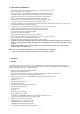
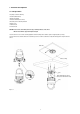
3. Installation and Configuration 3.1 Package Contents The package contains the following: 1x Fastrax IV (Dome Camera) 1x Bubble ring (optional) 1x Instruction manual (this document) 3x Assembly screws for attaching Fastrax IV 3x Plastic anchor 1x 10Pin Connector 2x 12Pin Connector CAUTION: B e sure to have caution labels (E version only) on both body and base of the camera. Different version will not support alarm input and output.
3.
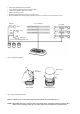
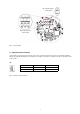
SW1: Termination switches Fail-Safe Network Addresses (ID) and protocol selection switches Figure 5 - Layout of Switches 3.3 Setting Dome Camera Termination The device which is connected at end of line, whether it be a dome camera or keyboard controller, must have the cable for communication terminated by setting the appropriate DIP switch. Without proper termination, there is potential for control signal errors. Total length of the cable for communication should not exceed 1.2km.
3.4 Fail-safe Network When you control the dome by the other device not own keyboard, some error may be existed in the serial communication. The reason is caused by the other device without the fail-safe network. At this time, you solve the problem to set this DIP switch to ON of the nearest dome from the other device only.
3.5 Setting Dome Camera Address (ID) To prevent damage, each dome camera must have a unique address (ID). When installing multiple dome cameras using a multiplexer, it is suggested that the dome camera address matches the multiplexer port number. If you want to set the address more than 999, you should connect the service provider. Example: Port 1 = Dome 1, Port 2 = Dome 2 ... Port 16 = Dome 16.
3.6 Setting Dome Camera Protocol If a dome camera is to be installed with a Fastrax keyboard controller, select the default protocol. Consult service personnel if a dome camera is installed with device other than a keyboard controller.
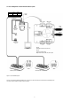
3.7 Connections • Connecting to the RS-485/-422 The dome camera can be controlled remotely by an external device or control system, such as a control keyboard, using RS-485 half-duplex, RS-422 full duplex or simplex serial communications signals. Connect Marked Tx+, Tx- to Tx+(Rx+) and Tx-(Rx-) of the RS-485 control system. If control system is RS-422, connect Rx+(Tx+), Rx+ (Tx-) and Rx+, Rx- of the dome camera to Rx+, Rx- and Tx+, Tx- of the control device respectively.
4. Program and Operation 4.1 Dome Camera Selection Before you program or operate a dome camera, you must select the dome camera by pressing the dome camera No. + CAM. Example: Pressing 1, 0 and CAM key sequentially will select dome camera 10. The selected dome camera ID will be displayed on the LCD monitor of the keyboard controller. 4.
4.4 Auto Scan (Shortcut: SCAN) The Auto scan supports up to 17 programmed angles at user-programmable speeds. NUMBER 01-08, 10-17, 09: AUTO PAN mode TITLE up to 12 characters MODE NORMAL, VECTOR, RANDOM (AUTO PAN mode: NORMAL, RANDOM only) NORMAL: Move from start point to end point in panning only. VECTOR: Move from start point to end point including tilt and zoom simultaneously and linearly. In some models, the zoom is fixed at wider angle and the zoom magnification information is not displayed.
9. Select „END ANGLE” and push the Joystick left or right. Hold down the CTRL key while moving the Joystick to select the end position. The end position angle should be larger than start position. Release the CTRL key to complete the selection of the end position. Or Press IRIS Open then the „CTRL” displays. Move the desired position and the zoom position. Press IRIS Close then the „CTRL” disappears. To adjust at the 0.1 degree interval, twist the Joystick at the pan field and the tilt field.
4.5 Preset (Shortcut: PRST) If you need to view specific places routinely, you should program presets. A preset is a programmed video scene with automatic pan, tilt, zoom, focus, and AE settings. Once programmed, placing the number position and pressing a PRST button on your controller calls up that preset automatically. In addition, presets may be assigned to alarm actions or as the „home” position for the dome camera.
5. After selecting a preset position, press and hold CTRL. Use the Joystick to control the direction of the camera and lens. 6. After aiming the camera (view direction and lens control), release CTRL. 7. Select „Event Function” and pushing the Joystick left or right. Then the event function setup displays. • Please refer to the below (4.5.1 Event Function) for more details. NOTE: The features will vary depending on the camera module installed in your dome camera. 8.
11. Select the preset list, then the stored preset list displays. Select the desired preset then the desired preset setup displays. NOTE: Press the HOME key at desired preset in preset table to delete a programmed preset . 4.5.1 Event Function You can set a preferred function in specified preset position. All available functions are like below. Motion You can detect a moving object in specified preset position.
Function Choose a function (None, Motion, Tracking, Cross, Enter, Abandon, Removal). Output Set the alarm output. (Off, Out1~Out4) Hold Time Set the hold time of alarm signal for chosen function, (Off, 03 – 99 seconds) 4.5.2 Motion You can detect moving objects in specified preset position. You can see the results by either „Bounding Box” or „Trace”. As a result of motion, screen will display the bounding box or trace. („Bounding box” means you can see a virtual rectangle on moving object.
Exclusion Area: You can set inactive area of Motion detection on this Menu. To avoid false alarm, we recommend you to exclude areas like trees with swaying branches or street with walking people. Set Area Locate the cursor on the “Set Area” and then twist Joystick and then move Green grid to the position. Change the colour of grid to disable Motion Detection by twisting Joystick. Then disabled Grid will be changed to Yellow colour.
4.5.3. Tracking You can make a camera follow the moving object automatically (In case of catching more than 1 moving objects at the same time, a bigger object will be tracked) Zoom Enable Set to enable or disable linked zoom capability during tracking. Return Time Set the dwell time before move to previous position once tracking is inactive. (Off, 3~99 seconds) Lost Mode Choose „Stop” or „Zoom Out” when object has been lost.
4.5.4 Cross You can detect a moving object crossing a specified virtual line (cross line) in a watch area. You can see current status of moving object by “Bounding Box”. („Bounding box” means you can see a virtual rectangle on moving object. In prior of this, you make sure that you set “On” in display and Bounding box in OSD Setup) Min. Set the min size of object while object crossed. Max. Set the max size of object while object crossed. Direction Set the direction while object cross.
4.5.5 Enter This can detect a moving object that newly enters in a specified area (enter box). You can see current status of moving object by „Bounding Box”. („Bounding box” means you can see a virtual rectangle on moving object. In prior of this, you make sure that you set “On” in display and Bounding box in OSD Setup. Min. Set the min size of object while object entered. Max. Set the max size of object while object entered. Base Set the reference point while object entered.
Min. Set the min size of object while object abandoned. Max. Set the max size of object while object abandoned. Event Time Set the event time. 10s, 20s, 30s, 40s, 50s, 60s, 70s, 80s, 90s, 100s, 120s, 180s, 240s Set Point Set the abandon box. Clear Remove the abandon box. Follow steps below to set the Abandon: 1. Set the min size of the enter object and set the max size. 2. Select the event time. 3. Select the „Set Point” then draw a box for two point. 4.
4.6 Shortcut of Preset Program After selecting the desired scene, press No. (1 to 240), and press CTRL and PRST subsequently. The current view will be stored to the selected preset number if the preset number is empty. If selected preset number is not empty, „Do you want to overwrite preset?” message will be displayed on the monitor and select the „OK” and push the Joystick to the right to overwrite. Example: 1 , 0 , 1 + CTRL + PRST will store current view as preset No. 101.
Dwell Set the dwell time at the both end, 01 – 99 seconds 5. Blank position mark (---) will be displayed and selected, then twist the Joystick. To add functions, select the preset, tour, pattern, and auto scan respectively. 6. You can also overwrite the programmed number and to remove a stored number from the Tour, press the HOME key on the stored number, a blank position mark (– – –) will be displayed. 7. Repeat Step 2 through 5 for each desired position.
4.8 Pattern (Shortcut: PTRN) The Pattern feature records user control of the selected dome camera. Up to four 8 patterns can be stored and played back by pressing No.+ PTRN keys subsequently. Follow steps below to program the Pattern: 1. Press MENU to display the main menu on the monitor. Scroll to Pattern and push the Joystick to the right to enter the pattern menu. Or just press the PTRN key on the keyboard. 2.
4.9 Alarm NO: Alarm input number PRIORITY: The lower number has higher priority. (1-8) FUNCTION: Stored function number to be called by alarm. IN: NO/NC - normally open/closed; OFF - ignore OUT: OUT1~OUT4 - Relay out 1,2,3,4, OFF - No output HOLD: Alarm will be held for programmed time (03 to 99 seconds) LATCH: ON - Shows all alarms including past alarm. OFF - Shows activated alarms only. DWELL: means the dwell time during multiple alarms, 03 to 99 seconds. There are 8 levels of priority.
You can set the schedule of Alarm operation on this menu. 4.10 Schedule You can set the schedule of Preset, Pattern, Tour, Auto Scan, Auto Pan, Origin, DIS On, DIS Off on this menu. Selected Function will be effective per selected start time and day (of the week) range.
Follow below steps to set schedule. 1. Locate cursor on the „+” and then, twist Joystick (keyboard) to add a new schedule. 2. To choose day (of the week) range, locate cursor on the relevant „Day” and then twist Joystick (keyboard) to set one of 10 ranges. (All, Mon, Tue, Wed, Thu, Fri, Sat, Sun, S-S, M-F) 3. To choose start time, locate cursor on the relevant „Start time” and then twist Joystick (keyboard) to set time. 4. Choose one function to work on this schedule.
4.12 Camera Menu (36x; EDC-4362, # 74224) NOTE: The features will vary depending on the camera module installed in your dome camera. 4.12.1 Auto Focus MODE AUTO / MANUAL / ONE PUSH / CONSTANT MANUAL Use manual mode in normal use. AF SENSITIVITY NORMAL / LOW NORMAL: Use this option when shooting fast motion. LOW: FOCUS LIMIT Offers better focus stability. In low luminance conditions, Auto Focus stops operation even when brightness changes, enabling stable images of moving objects. 9.5cm / 32cm / 1.
RGAIN 0 ~ 255 BGAIN 0 ~ 255 RGAIN / BGAIN modes are controllable only in MANUAL Mode 4.12.3 Auto Exposure MODE AUTO / MANUAL / IRIS PRIO / SHUTTER PRIO / BRIGHT AUTO: Auto Iris and Gain, Fixed Shutter speed (NTSC: 1/60 sec, PAL: 1/50 sec) MANUAL: Variable Shutter, Iris and Gain. IRIS PRIO: Variable Iris, Auto Gain and Shutter speed. SHUTTER PRIO: Variable Shutter speed, Auto Iris and Gain. BRIGHT: Variable Iris and Gain IRIS F1.6 / F2 / F2.4 / F2.8 / F3.4 / F4 / F4.8 / F5.6 / F6.
4.12.4 DIS (Digital Image Stabilization) DIS USE IMAGE SHOW ON / OFF Choose to enable or disable DIS NONE / PIP / PDP NONE: Only viewing DIS Active image PIP: View original image (small) and DIS active image (big) as picture in picture PBP: View original image (left) and DIS active image (right) as picture in picture NOTE: There might be malfunction of DIS for the following cases. • The camera is operating under extremely low light condition.
BRIGHT OFFSET -7, …, 0 (default), …7 Adjust the brightness level (AUTO, SHUTTER PRIO, IRIS PRIO mode only) SLOW RESPONSE The slow response function allows you to lengthen the automatic exposure response speed from 1 up to 32 times. For example, with the normal setting (about 1 second), if the headlights of a car are caught by the camera, the camera automatically adjusts the exposure so that it can shoot a high-intensity subject (in this case, the headlights).
MODE AWB / WAWB / INDOOR / OUTDOOR / MANUAL AWB: Computes the white balance value output using colour informatIion from the entire screen automatically (2500 to 9500K). WAWB: Wide range auto white balance mode (1800 to 10,500K) INDOOR: Indoor white balance mode OUTDOOR: Outdoor white balance mode MANUAL: Manual mode. You can change R and B Gain manually. RGAIN 0 ~ 255 BGAIN 0 ~ 255 RGAIN / BGAIN modes are controllable only in MANUAL Mode 4.13.
4.13.4 DIS (Digital Image Stabilization) DIS USE ON / OFF IMAGE SHOW NONE / PIP / PDP Choose to enable or disable DIS NONE: Only viewing DIS Active image. PIP: View original image (small) and DIS active image (big) as picture in picture. PBP: View original image (left) and DIS active image (right) as picture in picture. NOTE: There might be malfunction of DIS for the following cases. • The camera is operating under extremely low light condition.
2DNR(1), 2DNR(2) Select 2D noise reduction level (OFF / 001~007) 3DNR(1), 3DNR(2) Select 3D noise reduction level (OFF / 001~031) NOTE: DNR(1) applied when motor stopped. DNR(2) applied when motor moving. 4.14 OSD Setup Display ON / OFF All display or title will disappear when DOME OSD DISPLAY sets OFF Trace ON / OFF Choose to enable or disable Trace.
NUMBER: 01 - 16 TITLE: up to 12 characters SWAP: Swap the start point for the end point. 1. Select the „NUMBER” and set the desired number by pushing the Joystick left or right. 2. To edit the title, follow the procedure of the auto scan above to edit titles. 3. Select „START ANGLE”. Hold down the CTRL key while selecting the start position using the Joystick. Current panning position will be displayed. Release CTRL key to complete the selection of the start position.
3. Place the cursor at the title field. Twist the Joystick to enter the title edit mode. Follow the procedure of the auto scan above to edit titles. 4. To turn the stored zone On or Off, twist the Joystick handle or press Tele or Wide Key. 5. Set the method, „BLOCK” or „V.OFF (video off)” 6. Select the Save option by pushing the Joystick up or down. Save and exit the program by twisting the Joystick. Press ESC or select the Cancel to exit the program without saving.
4.17 Home Function Setup FUNCTION NONE / TOUR/ PATTERN / AUTO SCAN / PRESET FUNCTION NUMBER --- WAITING TIME 10~240 seconds FUNCTION ENABLE ON/ OFF The Home function can be set so that the camera automatically goes to Preset, Tour, Pattern, Auto Scan after the keyboard controller has been idle for certain time. For example, if the controller is idle for 120 seconds, the camera goes to preset 1.
TILT OVER ANGLE This option is used to set the limit of the horizontal view angle so that the trim ring or ceiling does not obstruct the horizontal image when zooming out (wide angle). ON: In some installations it is desirable for the dome camera to be able to see above the horizon. When this option is chosen, the dome will tilt up over the horizon (about -10 degrees). When the lens is zoomed out, you can see the ceiling line.
1. Place the dome camera under 90 degree vertically. 2. Set the right limit by pushing the Joystick to the right. 3. Set the left limit by pushing the Joystick to the left. 4. Set ENABLE to ON to use To exchange the right and the left limit, set SWAP to ON. To apply limits on the auto pan (endless panning), set AUTO PAN to ON. NOTE: When you use the panning range, we recommend using the flip mode to AUTO.
Pan Offset: Set on the viewing image of Pan Offset in Origin menu. Tilt Offset: Set on the viewing image of Tilt Offset in Origin menu. 4.20 Dome Reset This feature is used to re-calibrate the orientation of a selected dome camera. Origin offset value is not affected by this function.
4.21 System Menu LANGUAGE English / French / German / Italian / Polish / Portuguese / Spanish / Russian / Korean / Japanese / Chinese CALIBRATION ON (Auto origin check) / OFF MENU TIME OUT ON (5 mintues) / OFF (always menu display) DOME ANSWER ON / OFF (no acknowledge command from the dome) This option is helpful to escape the collision of the command using some DVR.
4.22 Function Run This Function Run menu allows you to execute the function when you use a keyboard or a DVR without the function keys (PRESET, PATTERN, TOUR and SCAN). 1. Select the desired Function by pushing Joystick Up or Down. 2. Select the number by twist the Joystick in PRESET, PATTERN, TOUR and SCAN. 3. Press CTRL or IRIS Open to execute. NOTE: To execute the function, you should store the function (PRESET, PATTERN, TOUR and SCAN) first. • HOME Select the HOME menu and press CTRL key.
4.23 Initialize Data FACTORY DEFAULT Select the Factory Default to initialize the Data. ERASE PROGRAMMED DATA Erase all stored data from the Flash-ROM of the selected dome camera. You will be asked to enter ON or OFF. If you desire to erase all data then select the Erase Run, otherwise press the ESC key to exit without erasing. The erased data includes all stored data (auto scan, presets, and tours….) except origin offset. The offset value is still valid after all data is erased.
4.24 System Information The system information provides essential information about the dome camera if service is required. When you view this screen, you can determine the camera type, ROM version. The information on this screen cannot be modified. 5. Troubleshooting If problems occur, verify the installation of the camera with the instructions in this manual and with other operating equipment.
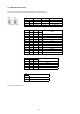
6. Specifications Type Art. No. EDC-4222 EDC-4362 74223 74224 Series eneo Fastrax IV Video standard CCIR/PAL System Day & night Sensor size 1/4” Imager Active picture elements Synchronization CCD, Sony ExView HAD Interline Transfer – 795(H) x 596(V) pixels Internal/AC line lock, phase adjustment via remote control Signal-to-noise ratio Sensitivity (at 50% video signal) Exposure modes Horizontal resolution 50dB 0.29 Lux, (colour) at F1.
Type Focal length Horizontal angle of view Digital zoom Aperture range (F) EDC-4222 EDC-4362 3.9 mm - 85.8 mm 3.4 mm - 122.4 mm 49.5° - 2.4° 57.8° - 1.7° 16x 12x F1.6~F3.6 F1.6~F4.5 Focus control Iris control MOD (Minimum Object Distance) Alarm inputs Automatic with manual override Auto iris, Manual override DC, auto iris, Manual override Wide angle (x1 to x4): 10cm; Tele end (x5 to x22): 1.0m 1.
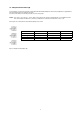
199 202 7. Dimensional Drawings R2.
APPENDIX A – Glossary Alarm Actions The assigned responses for the dome camera when inputs change from normal to abnormal states. The dome may run a Preset, Pattern, or have no assigned action for each of the four dome inputs. The dome may also send alarm states to the host controller for processing. See also Input and Normal Input State. Areas Programmed start and end points of the dome’s field of view around its pan axis. Each area is a part of a circular viewing area that extends around the dome.
APPENDIX B – Short Cut Key Short Cut Key PRST TOUR PTRN SCAN NO.
eneo® is a registered trademark of Videor E. Hartig GmbH Exclusive distribution through specialised trade channels only. VIDEOR E. Hartig GmbH Carl-Zeiss-Straße 8 · 63322 Rödermark/Germany Tel. +49 (0) 6074 / 888-0 · Fax +49 (0) 6074 / 888-100 Technical changes reserved. www.videor.com www.eneo-security.com © Copyright by VIDEOR E.