Installation and Operating Manual Network 1-Channel Video/Audio Server, MJPEG, H.
Contents 1. Safety Instructions / Maintenance........................................................................................................................3 2. Product Features.................................................................................................................................................4 3. 4. 5. 2.1 Product Introduction..................................................................................................................................4 2.
1. Safety Instructions / Maintenance • Read these safety instructions and the operation manual first before you install and commission the unit. • Keep the manual in a safe place for later reference. • The system may only be commissioned and maintained by personnel authorized to do this and it must only be carried out in accordance with relevant standards and guidelines. • Never cover the ventilation slots to avoid overheating. • Never insert metal objects or any other items into the vents.
2. Product Features 2.1 Product Introduction This video server is an ideal user-friendly device which brings digital benefits to your analog surveillance cameras. The tiny and compact body design can be easily installed in all kinds of analog cameras for network surveillance. The video server adapts Texas Instrument’s (TI’s) newest digital media processor - the Da Vinci DM 355 for efficient image operation, while also offering simultaneous dual-codec (H.
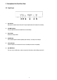
3. Description of the Front/Rear View 3.1 Front Panel 1. Act indicator Indicates the network status of the unit. The green light indicates the network is activating. 2. 10/100M indicator The green light indicates the network data are transmitting. 3. Reset button Recover to factory default. 4. SD CARD Slot This is used for system software updating and archiving / accessing critical images 5. Status indicator If this LED light is on, it means the SD card is recording or the device is updating. 6.
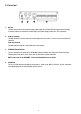
3.2 Rear Panel 1. DC jack The inlet connects to an external power supply. Connect with the 12 VDC/24VAC TUV-approved Power Supply; or connect with the UL Listed Class 2 Power Supply or ITE power supply marked ’LPS’ or its equivalent. 2. Video in connector The BNC connector is used to connect to the video output from the camera. 1 camera can be connected to the connector. Video out connector This BNC connector provides a video signal to the main monitor. 3.
3.3 ALARM I/O PIN Configuration 1. RS-485 pin: D+ 2. RS-485 pin: D– 3. GND1: Ground Contact 4. ALARM RESET (INPUT): This pin connects to an alarm-clear device for clearing an alarm ( 5V 0V(Active) ). 5. GND2: Ground Contact 6. ALARM IN 1 (INPUT): This is an alarm input which can be programmed in the menu system to Normally Open 5V or Normally Closed ( 0V(Active) ). 7.
3.4 The USB Function By connecting the video server board with a PC via the USB connector, the video server board can provide different functions. 1. Insert an SD card: As a card reader Insert an SD card into the Video Server, then connect to the PC. You might transfer files between the SD card and the PC. Once you’ve connected your Video Server to your computer, the Windows system will detect the connection and ask you what you want to do with your SD card.
3.5 PoE (Power over Ethernet) These technologies will enable the development of new networked appliances, by providing power as well as data over existing Ethernet cables. The Summary Comparison of PoE Standards (Table 1) is listed as follows. STANDARD Source Voltage 1 Table 1. Summary Comparison of PoE Standards SOURCE LOAD Ethernet RJ-45 connector pin number * DC Load Load 2 3 4 5 6 7 8 ConnecVoltage tor IEEE 802.3af 48VDC, RX, RX, using data protected DC+ DC+ pairs IEEE 802.
4. Installation Please follow the instructions below to set up the system. 4.1 Updating System Software If the system software of the Video Server needs to be upgraded, please take the following steps to safely process it. IMPORTANT: Before carrying out the following procedures, please ensure the SD card is working and the file of the system firmware is intact 1. Format an SD card using the FAT format if it is unformatted. 2. Create a directory named „VSERVER” in the SD card if it does not exist.
4.2 Video Server SD Card Troubleshooting 1. Check if the SD card position is correct or not. Please refer to the manual for the related information. 2. After powering the Video Server on, correctly insert the SD card, and a little icon of „SD” will show up in the upper-right corner of the monitor screen. If not, it means the device detection has failed. Please contact your technical support and ignore the following steps. 3. If no cross sign appears beside the „SD” icon, please go on to the next step.
5. Network Configuration 5.1 Cable Connections Please follow the instructions below to connect your Video Server to a computer or a network and to choose a proper RJ-45 cable configuration for connections. Physical specification of RJ-45 cable for Ethernet Wire Type Cat. 5 or above Connector Type RJ-45 Max. Cable Length 100m Hub Wiring Configuration Straight through or Cross Over PC Wiring Configuration Straight through or Cross Over 5.1.
5.1.2 Connect to a LAN Switch (INTRANET) The RJ-45 PIN configuration for connecting with a LAN Hub. to PC Network card to Network RJ-45 Switch 5.1.3 Connect to a PoE Switch The Standard RJ-45 PIN configuration for connecting with a PoE Switch is shown below. to PC Video Server RJ-45 PoE to Network RJ-45 RJ-45 Power Inlet (Using the supplied 48V power supply, connect to a wall power outlet.
5.2 Configure your Video Server Network Settings Upon connecting with the network hardware, you need to activate the network function and configure the proper network settings of the Video Server. 5.2.1 Enable DHCP Function The user can use the USB function (refer to section 3.4) or the Internet Explorer (refer to section 6.1.3) to enable the DHCP function. This function can only work if the LAN, which the unit is connected to, has a DHCP server.
When a Video Server is connected to a WAN, you must acquire a unique, permanent IP address and correctly configure the MASK and GATEWAY settings according to your network architecture. If you have any questions regarding those settings, please contact a qualified MIS professional or your ISP. NOTE: When connecting to a network, each connected Video Server must be assigned a unique IP, which must be in the same class type as your network address.
Click the Configuration tag, and check if the TCP/IP is included among the network components list. If the TCP/IP is included, please process section 5.5. If it is not included, please follow section 5.4 to install the TCP/IP. 5.4 TCP/IP Installation During the installation, you will be requested to insert the Windows CD-ROM. After installation, the PC may be restarted.
5.5 TCP/IP Configuration Setting Click Start –> Settings –> Control Panel –> Network Select TCP/IP, and then click Properties. Before processing the Video Server installation in a WAN, please make sure the Internet connection works properly. If not, please contact your ISP provider. If you are using a DHCP server, please select Obtain an IP address automatically. Any assigned IP address for the connected Video Servers must be in the same class type as the server.
5.6 Connection Testing With the previous settings, follow the instructions below to ensure whether you have established the connection successfully. Click Start –> Programs –> MS-DOS Prompt Type in ping 192.168.1.168 then Enter. (See the sample screen below) • This IP is the Video Server IP address that is assigned for the connected Video Server in step 2.
If you receive a response as in the sample screen below, the connection hasn’t been successfully established. Please re-check all the hardware and software installation by repeating steps 1 to 5. If you still can’t establish the connection after re-checking, please contact your dealer. If you receive a response as in the sample screen below, you have successfully made the connection.
6. Operating Instructions for Image Software and Network Two choices of software are available for linking with the Video Server: (1) the Microsoft Internet Explorer; and (2) the eneo GL-Manager, a network browser in a PC which provides the functions of monitoring remote zones or watching recorded data through the TCP/IP protocol. The details are listed as follows. RJ-45 PIN configuration for Ethernet PIN NO. PIN Assignment 1. TX + 2. TX - 3. RX + 4. Not Connected 5. Not Connected 6. RX - 7.
6.1 Microsoft Internet Explorer 6.1.1 Connecting the Video Server 1. Start up the Microsoft Internet Explorer, and then follow the steps below to connect the Video Server. 2. Click the URL block at the top of the window. 3. Enter the URL address of the Video Server into the URL block and press the „Enter” button to enter the home page. 4. Scroll to the bottom of the page, with its five icons, „Image”, „Network”, „System”, „Application”, „SD Card” and „Pan/Tilt”.
Browsing images from the Video Server The images from the Video Server will be displayed on the home page while going online with the Video Server. Some buttons of the home page are provided for further setting. Homepage of MJPEG mode Homepage of H.264 mode • Click the Image button to enter the image-setting page. • Click the Network button to enter the network-setting page. • Click the System button to enter the system-setting page. • Click the Application button to enter the application-setting page.
6.1.2 Change Image Setting Please follow the steps below to change the image setting through the network if necessary. 1. Click the Image button on the home page to enter the image-setting page. 2. Adjust the image setting including „Device Title” and „Viewer Type” if necessary. 3. Click the Submit button to submit the new image setting. 4. Click the Multi Profile button to enter the MultiProfile image-setting page. Select an ID (1-6) from the drop-down list then set its resolution and quality.
5. Click the H.264 Image button to enter the H.264 image-setting page. Adjust the image setting including „Resolution”, „Quality” and „Frame Rate” if necessary. 6. Click the Fine Tune button to enter the Image Fine Tune page to set the details of the device including: „Brightness”, „Contrast”, ”Hue” and „Saturation”. Click the Default button to reset the channel image settings. NOTE: The revised image will appear immediately after any change in made. 7.
Description of function keys Device Title: Type in the Video server title in the given space. Resolution: MJPEG mode - Scroll to choose the image resolution from „352 * 240”, ”720 * 240” or ”720 * 480” (NTSC); „352 * 288”, „720 * 288„ or „720 * 576„ (PAL). H.264 mode - Scroll to choose the image resolution from „Full D1”,”Half D1” or „CIF”. Quality: Scroll to choose the image quality out of a spectrum of qualities ranging from „highest”, ”high”, „medium”, and „low” to „lowest”.
3. The accessible networks here are the „FTP”, the „SMTP”, the „SNTP”, the „DDNS”, the „PPPoE” and the „IP Filter”. 4. Fill in the „IP Address”, „Netmask”, „Default gateway”, „Primary nameserver”, and „HTTP Port” if necessary. 5. Click the Submit button to submit the new network setting. 6. Click the Home button to return to the home page. Description of function keys IP Address: Enter the 4Byte IP Address in the appropriate blank space (the value in each box may be anywhere between 0 and 255).
Description of function keys FTP IP Address: Enter the FTP server DOMAIN NAME in the appropriate blank spaces. User Name: Fill in the FTP user name in the attached blank space (if the data is not provided, warning messages will show up). Password: Type in the FTP password in the attached blank space (if the space is blank, warning messages will show up). Upload Path: Enter the upload path while doing the FTP. Submit: Click to submit the new FTP setting to the Video Server.
• Change the Network Setting - SNTP Please follow the steps below to change the SNTP setting through the network if necessary. 1. Click the SNTP button at upper left above to enter the „SNTP Server Setting” page. 2. Enter the IP Address of the SNTP server, and choose one of the time zones as and when necessary. 3. Click the Submit button to submit the new SNTP setting. 4. Click the Home button to return to the home page.
• Change the Network Setting - DDNS The „Network” page has, on its upper left, the „DDNS” icon. Please follow the steps below to change the DDNS setting through the network if necessary. 1. Click the DDNS button at upper left above to enter the „DDNS SETTING” page. 2. Click the „Enable DDNS Function” to checkmark the attached box and activate the function. 3. Click „DDNS Type” to open the list of DDNS modes to choose from: „DynDNS” and „hn”.
• Change the Network Setting - PPPoE The „Network” page has, on its upper left, the „PPPoE” icon. Please follow the steps below to change the PPPoE setting through the network if necessary. 1. Click the PPPoE button at upper left above to enter the „PPPoE Setting” page. 2. Click the „PPPoE mode” to activate the function. 3. Type in the PPPoE „Account” and the PPPoE „Password”. 4. Click the Submit button to submit the new setting. 5. Click the Home button to return to the home page. NOTE: Please refer to 6.
• Change the Network Setting - UPnP The „Network” page has, on its upper left, the „UPnP” icon. Please follow the steps below to change the UPnP setting through the network if necessary. 1. Click the UPnP button at upper left above to enter the „Universal Plug and Play” page. 2. Click „Enable UPnP” to checkmark the attached box and activate the function. 3. Type in the UPnP „Max Expired Age”, the „SSDP Port” and the „UPnP Port”. 4.
• Change the Network Setting - IP Filter The „Network” page has, on its upper left, the „IP Filter” icon. Please follow the steps below to change the IP Filter setting through the network if necessary. 1. Click the IP Filter button at upper left above to enter the „Network Setting” page. 2. Click „Enable IP Filter” to checkmark the attached box and activate the function. 3. Select the Default policy. 4. Set the Allow/Deny IP Filter policy and enter its IP address. 5.
• Change the Network Setting - Network Traffic The „Network” page has, on its upper left, the „Traffic” icon. Please follow the steps below to change the UPnP setting through the network if necessary. 1. Click the Traffic button at upper left above to enter the „Network Traffic” page. 2. Type in the „Maximum Upload Bandwidth” and the „Maximum Download Bandwidth”. 3. Click the Submit button to submit the new setting. 4. Click the Home button to return to the home page.
6.1.4 Change the System Setting Please follow the steps below to change the date and time of the system setting through the network if necessary. • Set the Date and Time of the System 1. Click the System button in the home page to enter the „Date and Time” page (default). 2. Choose one of the three modes shown on the page to set the Date and Time of the system. The three modes are „Set Manually”, „Synchronize with Computer Time”, and „Synchronize with SNTP Server”. 3.
• Change the System Setting - Timestamp Please follow the steps below to change/add the timestamp through the network if necessary. 1. Click the Timestamp button on the left side of the „System” page to enter the „Timestamp” page. 2. Click „Enable Timestamp” to checkmark the attached box and activate the function 3. Add or modify any timestamp’s data if necessary. 4. Enter the „Timestamp Color” you have chosen. 5. Enter the „Timestamp Location” you have chosen. 6.
• Change the System Setting - Users Please follow the steps below to change/add the users’ authority through the network if necessary. 1. Click the Users button on the left side of the „System” page to enter the „Users” page. 2. Add, modify or delete any user’s data if and as necessary. 3. Click the Submit button to submit the new user’s setting. 4. Click the Home button to return to the home page.
• Change the System Setting - Digital I/O Please follow the steps below to change the Digital I/O through the network if necessary. 1. Click the Digital I/O button on the left side of the „System” page to enter the „Digital I/O Setting” page. 2. Mark „Digital Input” „ON” or „OFF”. Click your choices to enable. 3. Select from the drop-down list to modify the Active Type of the Digital Input or Digital Output. 4. Click the Submit button to submit the new user’s setting. 5.
• Change the System Setting - Audio Mechanism Please follow the steps below to change the Audio Mechanism through the network if necessary. 1. Click the Audio Mechanism button on the left side of the „System” page to enter the „Audio Mechanism Setting” page. 2. Mark „Audio Mechanism” „ON” or „OFF”. 3. Click the Submit button to submit the new user’s setting. 4. Click the Home button to return to the home page. NOTE: This setting is for turning the audio mechanism of the Videor Server on/off automatically.
• Change the System Setting – RS485 Setting Please follow the steps below to change the RS485 Setting through the network if necessary. Click the RS485 Setting button on the left side of the „System” page to enter the „RS485 Setting” page. Description of function keys Baud rate: Eight different speeds can be used: 2400 baud per second, 4800 baud, 9600 baud, 19200 baud, 28800 baud, 38400 baud, 57600 baud and 115200 baud. Type: Choose one of the types.
• Change the System Setting - Update Firmware Please follow the steps below to change the Audio Mechanism through the network if necessary. 1. Click the Update Firmware button on the left side of the „Date and Time” page to enter the „Update Firmware” page. 2. Click the „Browse…” button to select the UPDATE.BIN file which was copied into your computer. 3. Click the „Update” button. 4. DO NOT power off the Video Server while this update process is running.
• View the Event Logs Please follow the steps below to view events through the network if and as necessary. 1. Click the Events button on the upper left above to enter the „Event Log” page. 2. Choose one of the three buttons shown on the page to view an event when necessary. The three buttons are titled „First Page”, „Previous 20”, and „Next 20”.
6.1.5 Change the Application Setting Please follow the steps below to change the application setting through the network if necessary. • Change the Application Setting - FTP Application Setting Please follow the steps below to change the FTP setting via the network if and as necessary to upload recording data live. 1. Click the Application button on the home page to enter the „FTP Application Setting” page (default). 2. Enter the „Upload Rate” you have chosen. 3.
• Change the Application Setting - SD Card Application Setting Please follow the steps below to change the SD CARD setting via the network if necessary to upload recording data live. 1. Click the SD card button on the top left to enter the „SD-Card Application Setting” page. 2. You have an option as to which SD - card storage format to use, the MJPEG or the AVI. Click your selected format and click Submit to set it. 3. If it’s MJPEG you want, fill in the „Max MJPEG Numbers” entry. 4.
• Change the Application Setting - SMTP Application Setting Please follow the steps below to change the SMTP setting via the network if necessary. 1. Click the SMTP button on the left side to enter the „SMTP Application Setting” page. 2. Enter the attached file number as and when necessary. The maximum number which can be used is 8. 3. Click the Submit button to submit the new SMTP setting of the recording. 4. Click the Home button to return to the home page.
• Change the Application Setting - Language Setting Please follow the steps below to change the Language setting via the network if necessary. 1. Click the Language button on the left side to enter the „Language Setting” page. 2. You have an option as to which language to use. The default is „English” 3. Click your selected language and click „Submit” to set it.
2. Click „Enable Record - UPLOAD Via FTP” to checkmark the attached box and activate the function. 3. Click „Enable Record - Save Into SD card” to checkmark the attached box and activate the function. 4. Click the Submit button to submit the new setting of the recording. 5. Click the Home button to return to the home page. Description of function keys Enable Record - Upload Via FTP: Activates or deactivates the recording to the FTP server.
• Change the Application Setting - Alarm Application Enable Setting Please follow the steps below to change the setting via the network if necessary. 1. Click the Enable Alarm button on the left side of the record to enter the „Alarm Application Enable Setting” page. 2. Check / uncheck the trigger types of „Enable Alarm – Upload Via FTP”. 3. Check / uncheck the trigger types of „Enable Alarm – Save Into SD Card”. 4. Check / uncheck the trigger types of „Enable Alarm – Upload Via SMTP”. 5.
• Change the Application Setting - Alarm - Motion Detection Please follow the steps below to enable changes in the motion detection function of the alarm through the network if necessary. Set the motion detection: 1. Click the Motion Detection button on the left side of the Alarm to enter the „Alarm - Motion Detection” page. 2. Click and drag the left mouse button to across a targeted zone to draw a red rectangle on the image (coordinates provided below).
6.1.6 View the SD Card filrs Please follow the steps below to change the SD Card setting through the network if necessary. • Change the SD Card Setting - FILELIST of MEMORY CARD Please follow the steps below to change the setting via the network if necessary. 1. Click the „SD Card” button at the bottom of the home page to enter the page containing the „FILELIST of MEMORY CARD”. The page comes in two modes, the JPEG and the AVI (please refer to the „SD card Application Setting” page). 2.
6.1.7 Control the Speed Dome Click the Pan/Tilt button on the home page to open the Speed Dome Controller. 1. Click „Configure” to enter to the RS485 setting page (please refer to Change the System Setting – RS485 Setting). Select a Speed Dome device ID from the drop-down list on the Speed Dome Controller. The Controller will display the corresponding ID. 2. Each of the ten buttons under ’Set’ is connected with a specific position and angle of either panning or tilting of the camera.
6.1.8 PPPoE & DDNS Using the PPPoE 1. Install the XDSL software (obtained from your ISP dealer) in your PC. 2. Search your Video Server’s IP address: you can use your Network Viewer’s Scan IP program, or just connect the Video Server and the Video monitor. The monitor screen will show the IP address on its right side. 3. Installing an IP address in your PC or notebook.
7. Advanced Operation Question 1: How to set up the motion detection area and its sensitivity? How to record into the SD card for 30 seconds when the motion has been activated and use the Microsoft Internet Explorer to view the recorded files ? • Set up the motion detection 1. Click the Application button in the home page. 2. Click the Motion detection button on the left side of the page to enter the „MOTION DETECTION” page. 3.
Question 2: How to use the DynDNS to connect the Video Server by using its Sub Hostname via the Intranet ? • Set the DDNS function 1. Click the Network button in the home page. 2. Click the DDNS button on the left side of the page to enter the „DDNS SETTING” page. 3. Tick on the „Enable DDNS Function” to activate it. 4. Choose one of the DDNS Types from the drop-down list.
• Upload the recorded file via the FTP 1. Click the Application button in the home page. 2. Click the Enable button on the left side of the page to enter the „Record Application Enable Setting” page. 3. Tick on „Enable RECORD - UPLOAD via FTP”. 4. Click the Submit button to submit the setting. • Set the upload rate 1. Click the Application button. 2. Click the FTP button on the left side of the page to enter the „FTP Application Setting” page. 3.
8. Specifications Type GLS-2301H Art. No. 92551 Series eneo GL System PAL/NTSC System requirements Processor: Pentium IV, Core2 Duo; 2.8GHz; 512MB RAM; Microsoft Windows XP, Vista Compression standard MJPEG, H.264 Ethernet interface 10Base-T, 100Base-TX, RJ-45 Network protocols TCP/IP, IPv4, UDP, FTP, PPPoE, ICMP, ARP, DHCP, SMTP, DDNS, DNS, RTSP, IP Filtering Power over Ethernet IEEE 802.
Digital storage media 6 MB RAM (Pre alarm memory, MJPEG), SD card Access 16 Users simultaneous support Serial interfaces RS-485 Software upgrade SD card / HTTP (Web browser) / FTP / USB Text display Date and time Menu languages German, English, Italian, French, Polish, Dutch, Spanish, Schwedish, Finnish, Hungarian, Czech, Portuguese Password protection yes, Multi level (administrators and users), IP filtering, HTTPS Supply voltage 12VDC, 24VAC, PoE Power consumption 3.
9. Function of Client PC System requirement Windows 2000, XP or above Browser IE 6.x Live Monitor Max.
APPENDIX 1 Register as a DDNS Member The DDNS (dynamic domain name system) is a function which is provided by an American company. Please refer to www.dyndns.com. This chapter provides the user with the basic instructions on how to register a free DDNS service. Registering for a DDNS Enter the URL www.dyndns.com. In the upper right-hand corner of the main page, where there is an item, „Create Account”, as shown in Figure 1.
Set up the DDNS After creating the account successfully, please enter your user name and password in the upper right-hand corner of the main page to login, as shown in Figure 2. Figure 2 After you login successfully, a text will appear saying „My Services”, as shown in Figure 3.
Click „My Services” to enter the service page. Please click the „Add Host Service” item which is below the „My Hosts” item, as shown in Figure 4. Figure 4 Click „Add Host Service”, and its service items will appear. The Add Dynamic DNS Host item helps to add a new DDNS. Each member may have only one free account, and one free account can have only five DDNS. Click Add Dynamic DNS Host to enter the DDNS setting page as shown in Figure 5.
All we have to set in this page is the „Hostname” item. The user can choose a Sub Hostname as s/he likes from the right-hand side of the Hostname’s drop-down list. NOTE: You don’t have to set the „IP Address” in the same format as the device’s IP Address. It will renew the IP Address automatically. After finishing the setting, please press the „Create Host” button as shown in Figure 6.
APPENDIX 2 PoE Installation Method WARNING: Please follow the steps in this instruction carefully. Connecting these adapters incorrectly may result in damage to your network devices. 1.
2. IP Video Server POWER+DATA IN: Connect a CAT 5 RJ-45 straight- through cable from the POWER+DATA OUT port on the Power over Ethernet Injector. 3. Power over Ethernet Injector POWER+DATA OUT: Provides the data and power to the IP Video Server. Connect this port to the POWER+DATA IN port on the IP Video Server. POWER IN: Using the supplied 48V power supply, connect to a wall power outlet.
4. Connecting the IP Video Server: please take the following steps: Step 1: Insert one end of a Cat 5 Ethernet RJ-45 cable into the „LIN IN” port of the Power over Ethernet Injector. Connect the other end of the cable to your network switch or PC. Step 2: Plug one end of the Power adapter into the „POWER IN” port of the Power over Ethernet Injector and the other end into your electrical outlet. The installed connection looks the same as in Figure 1.
APPENDIX 3 FAQ 1. Can the SD Card be removed during recording ? A: No, it cannot be removed until the recording comes to a single point. The POWER LED flashing light signals the SD card is operating. The green light indicates the unit is activating. The red light warns the SD card cannot be removed. If the SD card is withdrawn in this mode, the card will break. 2. I’ve set the function of „Motion Detection” but it doesn’t seem to work.
eneo® is a registered trademark of Videor E. Hartig GmbH Exclusive distribution through specialised trade channels only. Videor E. Hartig GmbH Carl-Zeiss-Straße 8 · 63322 Rödermark/Germany Tel. +49 (0) 6074 / 888-0 · Fax +49 (0) 6074 / 888-100 V. 1.1 www.videor.com © Copyright by Videor E. Hartig GmbH 12/2009 Technical changes reserved.