Installation and Operating Manual 1/4” Day/Night Camera, Outdoor Housing, 22x Zoom VKC-1416B-/PP
Contents 1. Safety Instructions............................................................................................................................................................................................................................ 3 2. Introduction...................................................................................................................................................................................................................................... 3 2.
1. Safety Instructions • Read these safety instructions and the operation manual first before you install and commission the camera. • Keep the manual in a safe place for later reference. • P rotect your camera from contamination with water and humidity to prevent it from permanent damage. Never switch the camera on when it gets wet. Have it checked at an authorized service center in this case. • Never operate the camera outside of the specifications as this may prevent the camera functioning.
3. Camera Installation Installation of the camera must be performed by qualified service personnel in accordance with all local national electrical and mechanical codes must perform installation of the camera. Perform the following steps to install the camera 3.1 Package Contents • Camera VKC-1416B/PP • Instruction Manual • Mounting Kit 3.
3.3 Parts Name Carefully remove the contents from the box, and verify that nothing was damaged in shipment. 1 4 3 5 6 2 1 Sunshield 2 AF camera module 3 Mount base 4 Bimetal 5 Heater 6 Connection cable 7 Cable label 7 3.4 Installation There are two ways of installing the camera. 1. 2. Cable through the wall with mount base. Using the conduit knockout punched with the mount base.
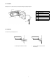
3.4.1 Installation 1 (Cable through the Wall with the Mount Base) A. Drill the mounting location, using the template sheet (or the bottom of the mount base) as a template. B. Insert the plastic anchors into the hole which has just drilled. C. Connect BNC cable and communication lines. D. Fit the screw holes of the mount base into the plastic anchors. E. Screw up the M6 torx screws (T-20). F.
3.4.2 Instillation 2 (Using the Conduit Knockout punched with Mount Base) A. Drill the mounting location, using the template sheet (or the bottom of the mount base) as a template B. Insert the plastic anchors into the hole which has just drilled. C. Connect BNC cable and communication lines. D. Fit the screw holes of the mount base into the plastic anchors. E. Remove the conduit knockout punched for the cable entry. F. Screw up the M6 torx screws (T-20). G.
4. Connection CAUTION: Do not connect the power cable until all other connections have been completed. if you complete the whole connection of cameras, then you have to cut the extra cable. Video (BNC) Monitor DVR / VCR (blue) (green) RS-485 connection (black/white) (gray) Day & night control (violet) (black) M/D control (orange) (black) A/D key control 4.
4.2 External Day/Night Control & Zoom Preset Control Is connect to an external sensor to receive day/night detection signals. External sensor switch ON/OFF GND (black) Day/Night EXT-IN EXT-OUT EXT-IN (gray) EXT-OUT (black/white) Day: open Night: closed Colour mode: 0V output B/W mode: 5V output Zoom Preset EXT Zoom Preset NOTE: To validate the sensor inputs, select Function menu B/W mode the EXT. 4.
4.5 Power Connection. POWER White (24VAC / 12VDC) Red (24VAC / 12VDC) CAUTION: Use certified/Listed Class 2 power supply transformer only. 4.
5. Settings in the OSD Menu 5.1 OSD Main Screen 1 AF 22X 2 MF 001X 3 CAM 001 1) Camera title 2) Status of the focus mode 3) Status of the zoom position 4) Camera ID 4 5.2 Main Menu FOCUS— ———————————— WB— ————————————— AE——————————————— BLC/WDR— ——————————— ALARM/MD/FD— ————————— PRIVACY— ——————————— SPECIAL— ——————————— EFFECT————————————— CAM SET END 1 2 3 4 5 6 7 8 5.2.
5.2.3 AE (Auto Exposure) Select Exposure mode. (INDOOR / OUTDOOR / SHUT PRI / MANUAL) MODE INDOOR OUTDOOR SHUT PRI MANUAL MODE SHUTTER GAIN DSS MAX DSS FLICKERLESS BRIGHTNESS END Indoor white balance mode Outdoor white balance mode Shutter priority exposure mode Manual exposure mode SHUTTER Select shutter speed. (1/60 (50)~1/100K) Can be changed while in SHUT PRI and Manual mode.
5.2.6 PRIVACY MASK SEL --- MASK SEL Select mask area number. (1~16) Select mask enable/disable. DEFAULT Set mask area as default. ADJ TOP/LEFT Adjust the location of the mask area with boundary top and left. DEFAULT ADJ BOT/RIGHT Adjust the location of the mask area with boundary bottom and right. ADJ TOP/LEFT COLOR ADJ BOT/RIGHT MOSAIC Mosaic display on/off COLOR MOSAIC TYPE Mosaic roughness setting. (1 ~ 4) MOSAIC MOSAIC TYPE Select mask colour.
5.2.9 CAM SET CAM ID BAUD RATE PROTOCOL DISP MODE DISP ITEM TITLE CAM ID Select the camera ID (1~255) BAUD RATE Select serial communication speed. (2400 / 4800 / 9600 / 19200bps) PROTOCOL Select operating protocol. (FASTRAX / PELCO-P / PELCO-D / COMMAND) DISP MODE Select display mode. (ON/OFF/PUSH ON) DISP ITEM 1 2 TITLE Select display item. (1~2) Camera Title and ID display Camera Title and ID, Zoom lens position display Select camera title menu.
8. Specifications Type Art. No.
Protection rating Alarm inputs Alarm outputs Supply voltage Power consumption Dimensions Weight Certificates IP66 – – 12VDC, 24VAC 9W See drawing 1.4 kg CE, IK10 Optional Accessories The optional accessories currently available can be found on our Homepage: www.videor.com 9. Dimensional Drawings 308 86 261 120 120 158 71.7 84 208 120 Dimensions: mm eneo® is a registered trademark of Videor E. Hartig GmbH Exclusive distribution through specialised trade channels only. Videor E.