LimbLogic® Prosthetist Instructions WHAT'S IN THE BOX Vacuum Pump* Battery Charger* Fob Fob Battery (quantity=2) Fob Key Ring Diagnostic Disc and Proximal Gasket (packaged together) Exhaust Port Drain Tube Replacement Exhaust Hose and Muffler* Thermoplastic Fabrication Kit or Lamination Fabrication Kit* Patient Instructions Prosthetist Instructions Quick-Start Guide *Quantity = 2 for bilateral kit This document provides instruction for the prosthetist in the installation and use of the system.
There are no field-serviceable parts inside the Vacuum Pump. Opening the Vacuum Pump will void the warranty. This pump is only designed to move air; use of Vaseline® or similar lubricating creams inside the socket will clog the pump. Do not allow foreign substances to be pulled through the Vacuum Pump. This may impair function of your vacuum system. Do not allow acetone to contact the Vacuum Pump or fob. LimbLogic is not intended to be used as the only means of attachment of prosthesis to patient.
TABLE OF CONTENTS Page Installing the Fob Battery.......................................................................... 4 Quick-Start Guide..........................................................................................5 Fob Guide.........................................................................................................5 Keys to Successful Use............................................................................... 6 Introduction...........................................
Overview INSTALLING THE FOB BATTERY The fob uses a commercially available CR2032 coin cell battery. The battery that is shipped with the system must be installed prior to using the fob. The battery will normally have to be replaced every 3 months depending upon how much the fob is used. The fob case can be pried open using a small flat blade screwdriver, then snapped back together starting at the battery end and working back toward the opposite end.
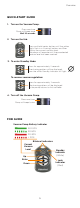
Overview QUICK-START GUIDE 1. Turn on the Vacuum Pump. Press one time. Pump will beep once. Wait 10 seconds. 2. Turn on the fob. Press and hold center button until the yellow digits flash in a “chasing” pattern and then display the current vacuum level. The pump will operate until the preselected vacuum level has been reached. 3. To enter Standby Mode: Press for approximately 2 seconds. The chasing pattern will be displayed, then the white Standby Indicator will light.
Overview KEYS TO SUCCESSFUL USE 1. Fabricate a non-porous Total Surface Weight Bearing socket using either a LimbLogic 4-Hole Attachment Plate or LimbLogic Drop-In Adapter. Fabricating an airtight socket is critical to the proper operation of the system. Be sure to follow the fabrication instructions provided with the adapter. Prior to delivering the prosthesis, you may want to use the Diagnostic Disc to confirm that there are no leaks in the system (refer to page 1 9). 2. Fully charge the Vacuum Pump.
Overview CHARGING THE VACUUM PUMP BATTERY The Vacuum Pump should be charged before it is used for the first time, at the end of each day of use, and when the Battery Indicator on the fob is red. Vacuum Pump Charger To AC outlet AC Adapter charging port charging plug LLV-21011 2012 Flashing: Charged 13.8 0V PN-1988-H ABN: 22582837497 solid: Charging 1.
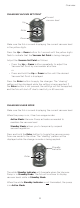
Overview TURNING ON THE VACUUM PUMP on/off button Press the on/off button on the Vacuum Pump one time. The Vacuum Pump will beep once. Before turning on the fob as described below, wait 10 seconds for the pump to activate. TURNING OFF THE VACUUM PUMP Press the on/off button on the Vacuum Pump and hold for 1 second. The Vacuum Pump will beep twice. Note: if the pump has just been unplugged from the Charger, it will be in Standby Mode (refer to page 9).
Overview CHANGING VACUUM SET POINT Current vacuum level Up Enter Down Make sure the fob is on and displaying the current vacuum level in the yellow digits. Press the Up or Down button for 1 second until the yellow digits flash to indicate that the Vacuum Set Point is being changed. Adjust the Vacuum Set Point as follows: • Press the Up or Down button repeatedly to adjust the Vacuum Set Point by one number at a time.
Overview If the pump detects a leak, the red Leak Indicator will illuminate, the usage mode will change to Standby Mode, and the pump will beep 10 times rapidly. The pump will repeat this every 30 seconds for 6 minutes unless acknowledged by pressing the on/off button on the pump. To return to Active Mode, press and hold the Enter button.
Overview CHANGING THE PROSTHETIST SETTINGS The system is shipped with the User Maximum set at 20 and the Vacuum Range set at 6. If these settings are not sufficient for your patient, you may adjust them as follows: Make sure the pump and fob are both turned on and are communicating with each other. Quickly press the Enter button on the fob three times to enable the Prosthetist Settings function. The three presses must be within approximately two seconds of each other.
Overview DETECTING A LEAK Leak Indicator If the Vacuum Pump detects a leak, the red Leak Indicator will illuminate, and the system will enter Standby Mode. At this time, the pump will make 10 short beeps. This will repeat every 30 seconds for 6 minutes unless acknowledged by pressing the on/off button on the pump. If the Leak Indicator appears when the patient initially dons the prosthesis, the patient should restart the pump.
Overview VACUUM PLATE/PYRAMID The Vacuum Plate (LLV-01043) and Vacuum Pyramid (LLV-01044) can be used for attaching the Vacuum Pump in line with other endoskeletal components, instead of attaching the pump directly to the socket. Use the Vacuum Plate and Vacuum Pyramid ONLY in the configurations shown here.
Overview EXHAUST TUBE MUFFLER CLEANING Using a flat blade screwdriver, remove the Exhaust Tube Fitting from the pump housing. Do not lose the o-ring from the fitting. Exhaust Tube Fitting Clear the clog in the tube by running water or by gently blowing compressesd air through the tube. If the clog cannot be cleared, purchase a replacement Exhaust Tube from WillowWood (LLV-21080). If the pump must be used before the replacement tube can be installed: 1.
Overview TROUBLESHOOTING GUIDE Problem Action The pump does not beep when the on/off button is pressed and the Charger is not connected to the pump. • The pump’s internal battery may not be charged. Charge the pump with the Charger for at least 30 minutes and try again. • The on/off button could be damaged. Verify that the rubber boot is intact and hasn’t been torn from impact. Contact WillowWood if the switch needs to be replaced. • The pump may have been exposed to a large static charge.
Overview Problem Action The fob does not communicate with the pump. The “chasing” pattern of LEDs ends after 6 seconds, and the LEDs turn off. • Wait one minute for the fob screen to turn off. Make sure the pump is on by pressing the on/off button and verify that the pump beeps once. Listen for about 30 seconds to make sure that the pump doesn’t quickly beep twice and turn off, which indicates a battery problem. Press the fob center button again. • The fob may be too close or too far from the pump.
Overview Problem Action The pump runs repeatedly. Using a flat blade screwdriver, remove the Exhaust Tube Fitting from the pump housing. Do not lose the o-ring from the fitting. Install the drain tube and flush the system with alcohol. The pump beeps but does not run. The Muffler on the Exhaust Tube may be clogged. Clean the Muffler as described on page 14.
Overview Error Codes If the vacuum pump’s controller detects an error from which it cannot recover, the fob display will alternate between the letters “Er” and a two-digit error code. Refer to the chart below for the type of error indicated by each code and the corresponding action.
Overview DIAGNOSTIC DISC The Diagnostic Disc included with the LimbLogic System can be used to test the vacuum pump as follows: 1. Remove the protective tape from the Diagnostic Disc. 2. Place the Proximal Gasket in the recess on top of the pump. 3. Place the Diagnostic Disc on top of the Proximal Gasket. 4.` Attach the pump with the Diagnostic Disc and Proximal Gasket to the socket. Be sure to tighten the bolts evenly; tightening them more on one side than the other may result in a leak. 5.
Technical Information The fob and the Charger are not water resistant. Submersion of the fob or the Charger will void the warranty. WARRANTY The warranty for the LimbLogic is two years from invoice date, provided that the system is selected according to the following criteria: Note: The weights listed below are adjusted body weights. Adjusted body weight is defined as the weight of the amputee plus any loads normally or routinely carried by the amputee.
Technical Information REGULATORY INFORMATION Return this product to the factory for proper dispoal. LimbLogic Fob This product contains a user replaceable lithium battery. Replace only with user replaceable CR2032 batteries. Discard of discharged batteries in accordance with local regulations. Observe polarity markings on the battery and the fob housing when replacing the battery. This product complies with: EN 60601-1-2:2007, IEC 60601-1-2 ED. 3.0, and IEC 60601-1:2005 +CORR.1(2006) + CORR. 2 (2007).
Technical Information LimbLogic Battery Charger This product is designed to work with WillowWood products specifically designed for its use. Use WillowWood charger part number LLV-21011. Use with other products may result in harm to the device, the user, or both and void the warranty. Refer to product manuals to verify compatibility with this charger before attempting to use this charger with the product. Electrical Ratings: Rated input: 100 – 240 Vac, 0.6 A, 47 – 63 Hz Rated output: 13.8 Vdc, 2.
Technical Information This digital apparatus does not exceed the Class B limits for radio noise emissions from digital apparatus set out in the Radio Interference Regulations of the Canadian Department of Communications. REMARQUE: Cet équipement a été testé et déclaré conforme aux les règles de ICES-001. Ces limites ont pour objectif de fournir une protection raisonnable contre les interférences nuisibles dans une installation résidentielle.
Technical Information Guidance and Manufacturer’s Declaration Electromagnetic Immunity LimbLogic is intended for use in the electromagnetic environment specified below. The customer or the user of the LimbLogic should assure it is used in such an environment. Immunity test IEC 60601 test level Compliance level Electromagnetic environment guidance Electrostatic discharge (ESD) IEC 61000-4-2 ± 6 kV contact ± 6 kV contact ± 8 kV air ± 8 kV Air Floors should be wood, concrete, or ceramic tile.
Technical Information Guidance and Manufacturer's Declaration Electromagnetic Immunity LimbLogic is intended for use in the electromagnetic environment specified below. The customer or the user of the LimbLogic should assure it is used in such an environment.
Technical Information Recommended separation distances between portable and mobile RF communications equipment and the LimbLogic LimbLogic is intended for use in an electromagnetic environment in which radiated RF disturbances are controlled.
USER PROFILE Prosthetist user LimbLogic is intended to be used for assembly of prosthetic devices by a certified prosthetist or prosthetic technician. Patient user LimbLogic is intended for use by patients meeting the following conditions. – Age: Any. Determined by clinician’s evaluation of patient competence and health. – Weight: (Body weight plus any loads normally or routinely carried cannot exceed these weight limits.) <350 lb (160 kg) for U.S. Activity K Level 2 or 3 <300 lb (136 kg) for U.S.
The Ohio Willow Wood Company 15441 Scioto Darby Road Mt. Sterling, OH 43143 phone 740.869.3377 / 800.848.4930 fax 740.869.4374 www.willowwoodco.com Ohio Willow Wood Company B.V Keizersgracht 62/64 1015 CS Amsterdam The Netherlands Patent www.willowwoodco.