Operating Instructions and Owner’s Manual INSTRUCTIONS CAREFULLY: Read heatstar mr. heater READ and follow all instructions. Place instructions in BY eNERCO a safe place for future reference. Do not allow anyone who has not read these instructions to assemble, light, adjust or operate the heater.
WARNING: WARNING: YOUR SAFETY IS IMPORTANT TO YOU AND TO OTHERS, SO PLEASE READ THESE INSTRUCTIONS BEFORE YOU OPERATE THIS HEATER. NOT FOR HOME OR RECREATIONAL VEHICLE USE WARNING: GENERAL HAZARD WARNING: FIRE, BURN, INHALATION, AND EXPLOSION HAZARD.
Important • Never block air inlet (rear) or air outlet (front). • In case of very low temperatures add kerosene to the heating oil. • Make sure heater is always under surveillance and keep children and animals away from it; • Before starting the heater always check free rotation of ventilator fan. • Unplug heater when not in use. Before using the heater, read and understand all instructions and follow them carefully.
Operation • Install the heater on a flat, level floor in a steady position. • It is forbidden to connect direct-fired heaters to air ducts. Before any attempt of starting the heater is made, check that your electrical supply conforms to the data on the model plate. Warning • • • • • Control Board 1 3 4 2 5 ON • • 0 • ON • 1 RESET BUTTON WITH CONTROL LAMP 2 CONTROL LAMP 3 MAIN SWITCH 4 ROOM THERMOSTAT PLUG 5 POWER CORD DO NOT USE GASOLINE, NAPHTHA OR VOLATILE FUELS.
The hot air generators with wheels must be wheeled. The suspended version which has no wheels must be transported with adequate machinery. Maintenance Preventive and regular maintenance will ensure a long trouble free life to your heater. Warning • Never service heater while it is plugged in, operating or hot. Severe burns or electrical shock can occur.
Troubleshooting TROUBLE Cause SOLUTION Motor does not start, no ignition No electrical current Check mains (should be 120 V – 1~ – 60 Hz) Check proper positioning and functioning of switch Check fuse Motor starts, no ignition or cuts out Wrong setting of room thermostat or other control Check correct setting of heater control.
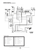
Wiring Diagram 4000 and 6000 Series Models Drawing Legend FU Fuse RV Control IT Transformer H.V. TA Room Thermostat LI1 Overheat Thermostat RE Relays EV1 Solenoid Valve 1° AP Control Box FO Photocell PA Air pressure control CO Condenser RF Heater filter MV Fan Motor FA Fan thermostat ST Electric pilot PE Ground ENERCO GROUP, INC.
4000DF and 6000DF Series Direct-Fired Portable Heater B 70 31 59 60 58 71 72 57 61 62 63 01 56 38 73 02 75 79 54 80 74 81 55 64 65 03 77 53 52 76 51 46 68 69 78 66 67 45 35 34 47 31 49 48 33 50 06 32 30 B 29 36 38 28 04 27 07 37 38 26 A 05 37 39 19 08 09 39 43 44 42 21 24 25 17 22 23 10 20 13 A 82 11 19 14 83 84 13 15 16 87 88 18 14 17 12 85 75 12 76 86 Operating Instructions and Owner’s Manual 8 ENERCO GROUP, INC.
4000DF and 6000DF Series Direct-Fired Portable Heater no. Stock No. 4000 01 G01 042-901 0 • G06139-9010 • G01040 • 02 G06140 03 G01038 G06143-9010 05 G01510-9010 G01500-9010 Stock No.
Operating Instructions and Owner’s Manual READ INSTRUCTIONS CAREFULLY: Read heatstar mr. Heater and follow all instructions. Place instructions in BY eNERCO a safe place for future reference. Do not allow anyone who has not read these instructions to assemble, light, adjust or operate the heater. Model Model 4000DF 6000DF 4000DF 6000DF WARNING: USE ONLY MANUFACTURER’S REPLACEMENT PARTS. USE OF ANY OTHER PARTS COULD CAUSE INJURY OR DEATH.
Guide d’utilisation et instructions de fonctionnement MR. HEATER Modèle Modèle 4000DF 6000DF LISEZ SOIGNEUSEMENT LES INSTRUCTIONS : Lisez et observez toutes les instructions. Conservez les instructions pour vous y référer ultérieurement. Interdisez à quiconque n’ayant pas lu les présentes instructions d’assembler, d’allumer, de régler ou de faire fonctionner cet appareil de chauffage. heatstar BY eNERCO 4000DF 6000DF AVERTISSEMENT: N’UTILISEZ QUE LES PIÈCES DE REMPLACEMENT DU FABRICANT.
4000DF and 6000DF Chauffage Portatif Direct-tiré G01 042-901 0 01 Stock No. no. 4000 G01040 G01038 6000 • G06139-9010 02 Disque pareflamme • • Chambre de combustion • G06143-9010 04 • G06142 G01500-9010 G01061-1 • E11231 09 • E10679-110 08 • G01061-2 G01513 • • • T10263 140329 17 G06104-9005 16 T20239 15 C30350 32 125019 31 M20202 30 C10546 29 Bouclier Carrosserie Inf.
60 59 31 70 B 57 72 61 62 63 58 71 56 38 01 79 75 65 64 54 80 55 81 74 73 02 53 51 76 46 68 69 78 66 67 52 77 03 4000DF and 6000DF Chauffage Portatif Direct-tiré 45 34 35 32 06 30 33 50 31 49 48 47 29 B 28 38 36 27 04 38 37 07 26 A 37 05 19 39 39 08 09 42 25 24 21 43 44 23 22 17 10 20 82 A 13 19 11 83 84 14 15 13 12 85 75 18 14 17 12 16 88 87 86 76 Le fait de Faire marcher des Instructions et le Manuel de Propriéta
Wiring Diagram 4000 and 6000 Series Models Dessin de la légende Commutateur RV Lampe temoin d’alimentation ST Moteur du ventilator MV Condensateur CO Photoresistance FO Electrovanne 2° EV2 Electrovanne 1° EV1 Thermostat de surchauffe LI1 Transformateur H.T. IT Fusible 20A FU TA RE AP FA CN RF LI2 PE Prise thermostat d’ambiace Relais Coffret de securite Thermostat ventilateur Connecteur Filtre gasoil rechauff Thermostat de securite de surchauffe Terre ENERCO GROUP, INC.
ANOMALIES DE FONCTIONNEMENT CAUSES ET SOLUTIONS Le courant électrique n’arrive pas Le ventilateur ne démarre pas et la flamme ne s’allume pas Cause ANOMALIE DEFONCTIONNEMENT SOLUTION Vérifier les caractéristiques de l’installation electrique (120 V – 1~ – 60 Hz) Vérifier le fonctionnement et la position de i’interrupteur Vérifier l’efficacité du fusible Le ventilateur démarre et la flamme ne s’allume pas ou ne reste pas allumée Vérifier les branchements des câbles d’allumage aux électrodes et au tran
surchauffe: le thermostat se réarme automatiquement quand la température de la chambre de combustion diminue jusqu’à rejoindre la valeur maximale admise. Avant de remettre en marche le générateur il faut trouver et éliminer la cause qui a produit la surchauffe (par ex. obstruction de l’entrée ou de la sortie de l’air, arrêt du ventilateur). Pour faire redémarrer le générateur il faut pousser le bouton de réarmement (1) et répéter les instructions spécifiques du paragraphe “MISE EN MARCHE”.
Tableau de commande 1 3 4 2 5 ON 0 ON CABLE ELECTRIQUE 5 PRISE THERMOSTAT D’AMBIANCE 4 INTERRUPTEUR MARCHE-ARRET 3 LAMPE TEMOIN D’ALIMENTATION 2 BOUTON REARMEMENT AVEC LAMPE TEMOIN 1 • REMPLISSEZ TOUJOURS LE RÉSERVOIR À L’EXTÉRIEUR, LOIN D’UNE FLAMME NUE. • N’UTILISEZ PAS DE SOURCE DE COMBUSTIBLE EXTERNE. • NE FAITES PAS FONCTIONNER L’APPAREIL DE CHAUFFAGE SI DES VAPEURS OU DES LIQUIDES INFLAMMABLES RISQUENT D’ÊTRE PRÉSENTS.
RECOMMANDATIONS GENERALES Le chauffage direct-tiré fonctionnent au fuel. Les générateurs à combustion directe répandent dans l’air ambiant, de l’air chaud et les produits de la combustion, alors que les générateurs à combustion in-directe sont dotés d’un raccord permettant d’éliminer les fumées à tra-vers un conduit de cheminée.
AVERTISSEMENT : VOTRE SÉCURITÉ PERSONNELLE ÉTANT IMPORTANTE POUR TOUS, VEUILLEZ LIRE LES INSTRUCTIONS AVANT D’UTILISER CET APPAREIL DE CHAUFFAGE. AVERTISSEMENT GÉNÉRAL DE DANGER : LE NON-RESPECT DES MESURES DE PRÉVENTION ET INSTRUCTIONS FOURNIES AVEC CET APPAREIL DE CHAUFFAGE RISQUE DE CAUSER LA MORT, DES BLESSURES GRAVES ET DES DOMMAGES OU DES PERTES MATÉRIELLES RÉSULTANT D’INCENDIE, D’EXPLOSION, DE BRÛLURE, D’ASPHYXIE, D’INTOXICATION AU MONOXYDE DE CARBONE OU D’ÉLECTROCUTION.
Guide d’utilisation et instructions de fonctionnement MR. HEATER Modèle Modèle 4000DF 6000DF LISEZ SOIGNEUSEMENT LES INSTRUCTIONS : Lisez et observez toutes les instructions. Conservez les instructions pour vous y référer ultérieurement. Interdisez à quiconque n’ayant pas lu les présentes instructions d’assembler, d’allumer, de régler ou de faire fonctionner cet appareil de chauffage.