Operating Instructions and Owner’s Manual enerRADIANT® HEATSTAR Model READ INSTRUCTIONS CAREFULLY: Read and follow all instructions. Place instructions in a safe place for future reference. Do not allow anyone who has not read these instructions to assemble, light, adjust or operate the heater.
WARNING: WARNING: YOUR SAFETY IS IMPORTANT TO YOU AND TO OTHERS, SO PLEASE READ THESE INSTRUCTIONS BEFORE YOU OPERATE THIS HEATER. FIRE, BURN, INHALATION, AND EXPLOSION HAZARD. KEEP SOLID COMBUSTIBLES, SUCH AS BUILDING MATERIALS, PAPER OR CARDBOARD, A SAFE DISTANCE AWAY FROM THE HEATER AS RECOMMENDED BY THE INSTRUCTIONS NEVER USE THE HEATER IN SPACES WHICH DO OR MAY CONTAIN VOLATILE OR AIRBORNE COMBUSTIBLES, OR PRODUCTS SUCH AS GASOLINE, SOLVENTS, PAINT THINNER, DUST PARTICLES OR UNKNOWN CHEMICALS.
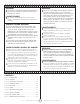
SECTION 1 SECTION 2 Introduction Planning Ener-Radiant ERXL models are low-cost, field assembled infrared heaters that are easy to install and require only minimal maintenance. They are designed to provide years of economical operation and trouble-free service. The following codes and instructions should be followed when planning the installation of the Ener-Radiant ERXL heater.
• When installed over hoists, minimum clearances to combustibles must be maintained from the uppermost point on the hoist. • Be sure the heater has a downward pitch of one-half inch per 20 feet away from the burner. • Provide signs in storage areas to specify maximum stacking height to maintain required clearances to combustibles. Electrical: The heater must be electrically grounded in accordance with the National Electrical Code, ANSI / NFPA-70 – latest revision.
ACCESSORY PARTS LIST Stock Number Description 10371.................................... Thermostat 24 volt 10392.................................... Thermostat 120 volt 17370.................................... Chain Kit 03445................................... Turbulator 10’ Section 03447................................... Turbulator 5’ Section 16401....................................24” Stainless Steel Flexible Gas Connector 18677A................................. Installation Manual F106414...........
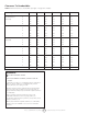
Clearances To Combustibles TABLE 1: Minimum Clearances to Combustibles (Use Figure 1 on page 10 as a Guide) Reflector Type Position ERXL-60 ERXL-80 ERXL-100 ERXL-125 ERXL-150 ERXL-175 Standard Reflector A 6” 6” 6” 6” 6” 8” (Horizontal) B 30” 36” 36” 36” 36” 36” C 55” 55” 74” 87” 87” 87” D 30” 36” 36” 36” 36” 36” A 12” 18” 18” 18” 18” 18” B 30” 36” 36” 36” 36” 36” C 55” 55” 74” 87” 87” 87” E 36” 36” 36” 36” 36” 36” F 60” 60” 60” 60” 60” 6
Clearances To Combustibles Clearances To Combustibles (Refer to TABLE 1 on page 9) Figure 1: A A C C D E Standard Reflector F 45° Reflector Tilt A C A D “U”-Tube, Standard A F C F “U”-Tube, Opposite 45° E F “U”-Tube, Full 45° C B Front and Back Clearance Enerco | enerRadiant® XL Series Heater B 7 Operating Instructions and Owner’s Manual
Parts List for Packaged Ener-Radiant XL Tube Heaters Item Stock# Description Number Required 1 F107400XL ERXL-60 NG COMP / 20’ 2 F107401XL ERXL-60 LP COMP / 20’ 3 F107402XL ERXL-80 NG COMP / 30’ 4 F107403XL ERXL-80 LP COMP / 30’ 5 F107412XL ERXL-80S, NG COMP / 20’ 6 F107413XL ERXL-80S, LP COMP / 20’ 7 F107414XL ERXL-100S, NG COMP / 30’ 8 F107415XL ERXL-100S, LP COMP / 30’ 9 F102650XL ERXL-60 NG / BRN & Cont Box 10 F102651XL ERXL-60 LP / BRN & Cont Box 11 F102652XL ERXL-80
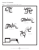
18 22 19 21 9 10 11 12 24 18 24 21 23 Figure “A” - Assembly Model ERXL-60, ERXL-80S 24 21 24 21 11 12 22 18 21 23 Figure “B” - Assembly Model ERXL-80 20 21 24 21 13 14 21 23 Figure “C” - Assembly Model ERXL-100s Enerco | enerRadiant® XL Series Heater 9 Operating Instructions and Owner’s Manual
Parts List for Packaged Ener-Radiant XL Tube Heaters Item Stock# Description Number Required 1 F107404XL ERXL-100 NG COMP / 40’ 2 F107405XL ERXL-100 LP COMP /40’ 3 F107406XL ERXL-125 NG COMP / 50’ 4 F107407XL ERXL-125 LP COMP / 50’ 5 F107408XL ERXL-150, NG COMP / 50’ 6 F107409XL ERXL-150, LP COMP / 50’ 7 F107420XL ERXL-175, NG COMP / 50’ 8 F107421XL ERXL-175, LP COMP / 50’ 9 F107416XL ERXL-125S, LP COMP / 40’ 10 F107417XL ERXL-125S, LP COMP / 40’ 11 F107418XL ERXL-150L, L
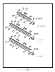
28 26 Figure “D” - Assembly Model ERXL-100, ERXL-125S Figure “E” - Assembly 28 Model ERXL-125, ERXL-150, ERXL-175 27 26 30 28 27 26 30 27 16 19 20 17 18 29 27 30 27 15 29 21 22 Figure “F” - Assembly Model ERXL-150L, 175L 19 27 Enerco | enerRadiant® XL Series Heater 11 21 29 Operating Instructions and Owner’s Manual 20 22 17 18
SECTION 3 Installation & Assembly FIGURE 2: Ener-Radiant XL Overview Key Burner Housing Must always be installed horizontally. Tube and Reflector Hanger Install immediately after first coupling. Reflectors Alternate overlap as shown on overview. Length of reflector and amount of overlap is indicated. 10' 2=1/2" Tube and Reflector Hanger Suspend system from these hangers. Minimum two (2) required per tube. Heat Exchange Tubes Supplied in 10 ft. lengths.
FIGURE 2c: Ener-Radiant XL Model ERXL-100S Assembly Overview 30 ft. Exchanger length. 31 ft. - 4 in. Total Heater length. 6 Suspension points as indicated. 18” Typ. HANGER 18” 18” HANGER 10’ 2-1/2” ALUMINIZED HANGER 18” 18” HANGER 18” 10’ 2-1/2” 10’ 2-1/2” ALUMINIZED (2) Turbulator Sections (1) Turbulator Adapter FIGURE 2d: Ener-Radiant XL Model ERXL-100, ERXL-125S 40 ft. Exchanger length. 41 ft. - 4 in. Total Heater length. 8 Suspension points as indicated. 18” Typ.
3) Attach the wire to the hole in the tab on the adapter piece. Assemble the heater components as shown in Figures 2a, 2b, 2c, 2d, 2e, and 2f. Optional reflector configurations are shown in (Figure 1). Install appropriated suspension hardware, beam clamps, chain or rod at predetermined locations. Adjustment of chain length will provide uniform pitch. 4) Using the wire, pull the assembled turbulator into the tube from the opposite side. 5) Pull the turbulator through until just the tab comes out.
FIGURE 5: Typical Suspension Details Screw Hook min. 3/8" (10 mm) Beam Clamp Washer I-Beam FIGURE 8: Burner Box / Transition Tube Detail Bar Joist Clip Concrete Beam Truss Locknut Burner Box (flame observation window facing down) Anchor Washer Wood Beam Mounting Flange As Req'd Gasket Stk. #12397 S-Hook Split Lock Washer Stk. #98527 Chain kit - Stk. #17370 Cap Screw Stk. 398012 One chain kit will suspend one 10 ft. section of tube and one 10 ft. section of reflector.
Section 4 recommended with unvented heaters due to pressure considerations. Horizontal Venting Venting / Ducting a) In combustible or noncombustible walls, use Tjerblund VH1-4” (Stk. #19022). Follow vent manufacturer’s instructions for proper installation. (Alternative vent Enerco Stk. #19023). b) Four (4”) inch O.D. flue pipe is required. Thirty (30’) feet maximum length is recommended. Up to forty-five (45’) feet maximum may be used if insulated to prevent excess condensation.
FIGURE 13b: Double Wall streams of combustion gases. Double wall vent run and Outside Air Supply a) Double wall terminal end See procedure and diagram on page ??. FIGURE 12: Unvented Operation A 36” 36” 1) Ventilation equal to 4 CFM per 1,000 BTU/hr. firing rate must be provided in unvented heater installations. 2) For dimensions A “unvented” refer to (Figure 1 — Minimum Clearances to Combustibles.
FIGURE 15: Common Roof Venting Approved Vent Cap Type "B" Vent required outdoors. H side view Roof Secure all joints with 3 (minimum) #8 x 3/8" sheet metal screws and seal all joints. Vent Adapter Stk. #19021 plan view At least 1/4" per foot rise or pitch must be maintained on horizontal runs from heater to vent. COMMON VENTING - (2) Heaters COMMON VENTING - (4) Heaters Model # H = 6 ft. H = 8 ft. H = 15 ft. Model # H = 6 ft. H = 8 ft. H = 15 ft.
Section 6 Outside Combustion Air Supply The Ener-Radiant XL heater is approved for installation with an outside air supply system. Some compounds such as halogenated hydrocarbons or other corrosive chemicals in the air can be drawn into the equipment and cause an accelerated rate of corrosion of some of the heater components. The use of such chemical compounds near the enclosure should be avoided. Gas Piping Read applicable warnings in (Section 1) before proceeding with Gas Pipe installation.
Section 6 FIGURE 20: Ener-Radiant XL Burner Internal Wiring Gas Valve Transformer Blue Green THERMOSTAT Yellow Green Supply Circuit 120v – 60 Hz Black White Black Terminal Bushing Air Switch H T Motor / Blower H White 120v – 60 Hz Black White Black Black White Purple Black VAC Burners (Maximum – 2 per Thermostat) Burners (Maximum – 2 per Thermostat) T Orange 24V 120 FIGURE 18a: Line Voltage Thermostat Wiring Black White 120V White Heaters are normally controlled by thermostat
Section 7 7. Check the flue pipe for soot or dirt. After cleaning as necessary, re-attach the flue pipe to the heater. Operation & Maintenance 8. Outside surfaces of heater may be cleaned by wiping with a damp cloth. Sequence of Operation 9. A qualified service agency should be contacted for service other than routine maintenance. 1. Turn the thermostat up. When the thermostat calls for heat, blower motor will energize. 2.
Natural outlet pressure should be 3.5” Honeywell Valve LED Status LP inlet pressure should be 11.0” The Ener-Radiant XL series Tube Heater is equipped with a honeywell Smart Valve. This valve has a built-in diagnostic program, which will assist in troubleshooting in the event of a valve-related problem. The LED or (Light Emitting Diode) is located on the top of the valve as shown in diagram below. The LED status indications are listed below to help with the troubleshooting.
SECTION 8: Troubleshooting Guide. Ener-Radiant XL START Turn on thermostat Does blower turn on? Check Thermostat and Wiring. Is the Yes power supply to unit 115V? No Is blower side door in place? No Find the source of the electrical problem Yes Is the air intake or exhaust blocked? No Remove door. Is voltage at door switch 115V? No Replace door Check voltage at gas valve. Check voltage to motor. Is it 115V? No Check wiring and hose connection to air switch.
Section 9 Replacement Parts 3 SIDE VIEW 8 2 10 6 5 9 4 11 1 TOP VIEW Item Part Number Description 1 02731 Hot Surface Igniter 2 02730 Flame Sensor 10413A Air Sensing Switch (ERXL-60, 80, 100, 125) 10414A Air Sensing Switch (ERXL-150, 175) 4 01391A Door Switch 5 02371 3 Cup Assembly Burner 6 07376 Motor and Blower Assembly 7 17376 Manifold 3 8 00016 2 7 SIDE VIEW 8 Gas Valve - Natural Gas 00017 Gas Valve - LP Gas 9 12404 Inspection Window 10 08364A Transformer
Section 10 Engineering Specifications Burner Ratings and Heat Exchanger Lengths: (Natural and LP) The total heating system supplied shall be design certified by the American Gas Association and the Canadian Gas Association. A. Burner & Burner Controls 1. Burners shall be capable of firing with one of the fuel options as specified on the purchase documents: Natural Gas or LP. 2. Burners shall be supplied to fire at any one of the input rates as specified. ERXL-60 60,000 BTU/Hr. ERXL-125 125,000 BTU/Hr.
FIGURE 25: Ener-Radiant XL Dimensions & Suggested Mounting Heights Minimum Total Length (see chart below) Minimum Total Length (see chart below) Turbulator (some Models) Reflector XL 17.75” Heat Exchanger Tubing Burner Side View 9.25” 13.75” Burner Rear View Enerco | enerRadiant® XL Series Heater 26 Model # Minimum Total Length Suggested Min.
this page intentionally left blank.
Operating Instructions and Owner’s Manual HEATSTAR Model ERXL-60 ERXL-80 ERXL-100 ERXL-125 ERXL-150 ERXL-175 ERXL-80S ERXL-100S ERXL-125S ERXL-150L ERXL-175L WARNING: USE ONLY MANUFACTURER’S REPLACEMENT PARTS. USE OF ANY OTHER PARTS COULD CAUSE INJURY OR DEATH. REPLACEMENT PARTS ARE ONLY AVAILABLE DIRECT FROM THE FACTORY AND MUST BE INSTALLED BY A QUALIFIED SERVICE AGENCY. FOR INFORMATION REGARDING SERVICE OR PARTS: Contact your local heating service technician or dealer.