Installer: Leave this manual with the appliance. Consumer: Retain this manual for future reference. Operating Instructions and Owner’s Manual Model # MHVFBI10LPT READ INSTRUCTIONS CAREFULLY: Read and follow all instructions. Place instructions in a safe place for future reference. Do not allow anyone who has not read these instructions to assemble, light, adjust or operate the heater. For model serial numbers, see page E16.
This appliance may be installed in an aftermarket* permanently manufactured (mobile) home, where not prohibited by local codes. This appliance is only for use with the type of gas indicated on the rating plate. This appliance is not convertible for use with any other gas. *Aftermarket completion of sale, not for the purpose of resale, from the manufacturer. WARNINGS • IMPORTANT: Read this owner’s manual carefully and completely before trying to assemble, operate, or service this heater.
SPECIFICATIONS MHVFBI10LPT BTU (Available) 10,000 Type of Gas LP-Gas Only Ignition Piezo Pressure Regulator Setting 10 Inches of Water Inlet Gas Pressure (Maximum) 14 Inches of Water Inlet Gas Pressure (Minimum) 11 Inches of Water Burners / Orifice nozzles 1 Thermostatic Control Yes Clearances: inches (mm) Top 36” (915cm) Sides 6” (152cm) Floor (min.
SAFETY DEVICE b. Whether stripping has been added on openable windows and doors, and c. Caulking or sealants are applied to areas such as joints around windows and door frames, between wall-ceiling joints, between wall panels, at penetrations for plumbing, electrical, and gas lines, and at other openings. If you home does not meet all of the three criteria above, see Determing the Type of Heater Location Space, below. This heater has a pilot with an Oxygen Depletion Sensor (ODS) safety shut off system.
heater, Gas furnace, Vented gas heater, Gas fireplace logs, and Other gas appliances* *Do not include direct-vent gas appliances. Directvent draws combustion air from the outdoors and vents to the outdoors. Example: Gas water heater 40,000 Btu/hr Vent Free Heater + 20,000 Btu/hr Total =60,000 Btu/hr 4. Compare the maximum Btu/hr the space can support with the actual amount of Btu/hr used.
WARNING: A qualified service person must install heater. Follow all local codes. For convenience and efficiency, install the heater: • CHECK GAS TYPE Use only LP-gas. If your gas supply is not LP-gas, do not install heater. Call dealer where you bought heater for proper type heater. • In the coldest part of the room.
1. Attach to wall studs 2. Attach to wall anchor 3. Insert mounting screws through bracket and into wall studs. 4. Tighten screws until mounting bracket is firmly fastened to wall studs. Attaching to Wall using Anchor: For attaching mounting bracket to hollow walls (wall areas between studs) or solid walls (concrete or masonry) Note: Wall anchors, mounting screws, and spacer are in hardware package. The hardware package is provided with heater. 1. Drill holes at marked locations using 5/16” drill bit.
Screw hole location, heater may be locked into position using anchoring holes in mounting feet. Note: Use of floor mounting feet will require you to use a 3/8 NPT street elbow to make gas connection. Screw hole Figure 10 CONNECTING TO GAS SUPPLY 2. Mark screws locations on wall. 3. Remove heater from mounting bracket. 4. If installing bottom mounting screw into hollow or solid wall, install wall anchors. Follow steps 1 through 4 under Attaching to Wall using Anchor.
1. Close equipment shutoff valve (see figure 13). 2. Pressurize supply piping system by either using compressed air or opening propne/LP supply valve. 3. Check all joints from the propane/LP supply valve to equipment shutoff valve (see figure 14). Apply mixture of liquid soap and water to gas joints. Bubbles forming show a leak. 4. Correct all leaks at once. 5. Depressurize and relieve pressure from supply piping system.
8. Turn off heater (see To Turn OFF Gas to Appliance, page 10. 9. Replace lower front panel. be depressed for about 30 seconds. This will allow air to bleed from the gas system. 6. Push in control knob and rotate control knob back to OFF position then rotate counterclockwise to PILOT/IGN position. This will light pilot. If needed gently keep rotating control knob back and forth while depressed until pilot lights. 7. Keep control knob depressed in for ten (10) seconds after lighting pilot.
INSPECTING BURNER Check pilot flame pattern and burner flame pattern often. PILOT FLAME PATTERN Figure 21 show a correct pilot flame pattern. Figure 22 shows an incorrect pilot flame pattern. The incorrect pilot flame pattern is not touching thermocouple. This will cause the thermocouple to cool. When the thermocouple cools, the heater will shut down. If pilot flame pattern is incorrect, as shown in Figure 22: • Note: Your heater may have either pilot assembly.
TROUBLESHOOTING NOTE: All troubleshooting items are listed in order of operation and likely occurrence. WARNING: Only a qualified service person should service and repair heater. CAUTION: Never use a wire needle, or similar object to clean ODS/pilot. This can damage ODS/pilot unit. Make sure grille guard is in place before running heater. If screen or grille guard is removed for servicing it must be replaced prior to operating the heater.
OBSERVED SYMPTOM POSSIBLE CAUSE REMEDY Heater shuts off in use (ODS operates) 1. Not enough fresh air is available 2. Low line pressure 3. ODS/pilot is partially clogged 1. Open window and/or door for ventilation 2. Contact local gas company 3. Clean ODS/pilot (see Cleaning and Maintenance, page 11) Gas odor even when control knob is in OFF position 1. Gas leak. See WARNING statement at top of page 2. Control valve is defective 1.
Unvented Liquid Propane Fired Room Heater E14 Installation Instructions and Owner’s Manual
70828 Unvented Liquid Propane Fired Room Heater E15 Installation Instructions and Owner’s Manual
Operating Instructions and Owner’s Manual Model # MHVFBI10LPT READ INSTRUCTIONS CAREFULLY: Read and follow all instructions. Place instructions in a safe place for future reference. Do not allow anyone who has not read these instructions to assemble, light, adjust or operate the heater. WARNING: USE ONLY MANUFACTURER’S REPLACEMENT PARTS. USE OF ANY OTHER PARTS COULD CAUSE INJURY OR DEATH. REPLACEMENT PARTS ARE ONLY AVAILABLE DIRECT FROM THE FACTORY AND MUST BE INSTALLED BY A QUALIFIED SERVICE AGENCY.
Instalador: Deje este manual junto con el artefacto. Consumidor: Conserve este manual para referencia futura. INSTRUCCIONES DE INSTALACIÓN Y MANUAL DEL USUARIO MR. HEATER ModelO MHVFBI10LP LEA CUIDADOSAMENTE LAS INSTRUCCIONES: Lea y siga todas las instrucciones. Conserve estas instrucciones en un lugar seguro para futura referencia. No permita que nadie que no haya leído estas instrucciones arme, encienda, ajuste o use el calentador.
Este artefacto puede ser instalado en una casa (móvil) del mercado de postventa* fabricada de manera permanente, si no estuviese prohibido por las normas locales. Este artefacto sólo se debe usar con el tipo de gas indicado en la placa de especificación. Este artefacto no se debe convertir para usarlo con otro tipo de gas. * Postventa, no para la reventa, directamente del fabricante. 4.
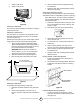
ESTABLECIENDO UNA VENTILACIÓN ADECUADA Características del producto Perilla de control Control Knob Quemador Burner Rejilla Grill Gabinete Heaterdel calentador Cabinet PanelPanel frontal Front Figura 1 DISPOSITIVO DE SEGURIDAD Este calentador tiene un piloto con un sistema de seguridad de Sensor de disminución de oxígeno (ODS). El ODS/piloto apaga el calentador si no hay suficiente cantidad de aire fresco. SISTEMA DE ENCENDIDO El calentador está equipado con un encendedor manual Piezo.
Nota: el espacio incluye el cuarto en donde instaló el calentador y los cuartos contiguos que tienen pasillos sin puertas o rejillas de ventilación entre ellos. 1. Obtenga el volumen del espacio multiplicando largo x ancho x altura del cuarto. Ejemplo: Tamaño del espacio 5,5 m (18 pies) (largo) x 5,5 m (18 pies) (ancho) x 2,5 m (8 pies) (altura) = 790 m3 (2592 pies3).
Ventilación del exterior UBICACIÓN DEL CALENTADOR Si fuera necesario permita la entrada de aire fresco adicional haciendo uso de conductos o rejillas de ventilación. Conecte estos artículos directamente al exterior o a espacios abiertos al exterior. Estos incluyen áticos* y espacios debajo del piso. Siga la Norma nacional de gas combustible (National Fuel Gas Code) NFPA 54/ANSI Z223.1, Artículo 5.
6-1/2”cm Min. 10,000Mín. BTU 10.000 BTU 16,5 (6-1/2") MONTAJE DEL CALENTADOR A LA PARED Soporte de montaje Pared contigua Adjoining Wall El soporte de montaje está ubicado en el panel trasero del calentador (remítase a la figura 5). Se ha colocado ahí con cinta adhesiva para su envío. Retire el soporte de montaje del panel trasero. Soporte de Mounting montaje Bracket 30,8 cm (Sm) (Sm) 12-9/64” (12-9/64") 44,417-1/2” cm (17-1/2") Min. Mín.
Cómo colocar el calentador sobre el soporte de montaje 1. 2. CUIDADO: Nunca conecte el calentador directamente al suministro de Propano. Este calentador requiere de un regulador externo (no suministrado). Instale el regulador externo entre el calentador y el suministro de Propano/LP. El instalador debe proveer un regulador externo. El regulador externo reduce la presión de gas entrante a entre 28 y 30 cm (11 y 14 pulgadas) de agua.
CÓMO REVISAR LAS CONEXIONES DE GAS ADVERTENCIA: Verifique que todas las conexiones y tuberías de gas no tengan pérdidas después de la instalación o el servicio de mantenimiento. Repare todas las pérdidas de inmediato. INSTRUCCIONES DE ENCENDIDO/OPERACIÓN PARA USO CON MANGUERA CONECTADA A UN CILINDRO REMOTO, TAMAÑO MÁXIMO DE 9 KG (20 LIBRAS) • ADVERTENCIA: Nunca use una llama para verificar si hay una pérdida de gas. Aplique una mezcla de jabón líquido y agua en todas las juntas.
Abierto Open estado bajo el agua. INSTRUCCIONES DE ENCENDIDO 1. Válvula de Equipment cierre del Shutoff Valve equipo ¡DETÉNGASE! Lea toda la información de seguridad incluida con del calentador y la del costado del mismo. 2. Verifique que el suministro de gas al calentador esté abierto. 3. Gire la perilla de control de gas en sentido horario hasta la posición "OFF" (apagado), (remítase a la figura 16). 4. Espere cinco (5) minutos. Luego fíjese si siente olor a gas, incluso cerca del piso.
Botón encendido IgnitordeButton el calentador se apagará. Si el patrón de la llama del piloto es incorrecto, como se muestra en la Figura 22: • Apague el calentador (remítase a Cómo cerrar el gas hacia el artefacto, página 11 para los modelos que no tienen termostato). • Remítase a Resolución de problemas, páginas 14 y 15.
Asegúrese de que la rejilla de protección esté en su lugar antes de encender el calentador. Si se saca la pantalla o rejilla de protección para su mantenimiento, la misma se debe volver a colocar antes de poner el calentador en funcionamiento. ADVERTENCIA: Si no mantiene la/s salida/s principal/es del quemador limpias, esto puede formar hollín y causar daños materiales. CÓMO LIPIAR EL SDO/PILOTO Y EL QUEMADOR • Utilice una aspiradora, aire presurizado o un cepillo de cerdas suaves para limpiarlo.
RESOLUCIÓN DE PROBLEMAS NOTA: Todos los problemas están enumerados en orden de operación y posibilidad de que ocurran. ADVERTENCIA: Sólo un técnico de mantenimiento calificado debe realizar el mantenimiento y reparar el calentador. CUIDADO: Nunca use una aguja de metal u objeto similar para limpiar el SDO/piloto. Esto puede dañar el SDO/piloto. Asegúrese de que la rejilla de protección esté en su lugar antes de encender el calentador.
El quemador no se enciende cuando el SDO/ piloto está encendido. 1. 2. 3. El orificio del quemador está obstruido. El diámetro del orificio del quemador es demasiado pequeño. La presión del gas de entrada de es muy baja. 1. 2. 3. Limpie el orificio del quemador (remítase a Limpieza y mantenimiento, página 11), o reemplace el orificio del quemador. Reemplace el orificio del quemador. Llame a la empresa de gas local. El quemador tarda en encender. 1. 2. La presión del colector es muy baja.
REPUESTOS Cómprele los accesorios del calentador a su distribuidor local. Si no pueden suministrarle estos accesorios, contáctese con la central de piezas más cercana o comuníquese con el número 800 de Enerco Group, Inc. para obtener mayor información. También puede escribir a la dirección que aparece en la parte de adelante de este manual. Válvula de cierre del equipo Para todos los modelos, válvula de cierre con acople de 1/8" NPT. Nota: use solamente repuestos originales.
CALENTADOR MONTADO A LA PARED, A GAS LP, SIN VENTILACIÓN ARTÍCULO NÚMERO DE PIEZA DESCRIPCIÓN CANT.
Instrucciones de uso y manual del usuario Modelo N.° MHVFBI10LPT LEA CUIDADOSAMENTE LAS INSTRUCCIONES: lea y siga todas las instrucciones. Consérvelas en un lugar seguro para futura referencia. No permita que nadie que no haya leído estas instrucciones arme, encienda, ajuste o use el calentador. ADVERTENCIA: USE SÓLO LOS REPUESTOS PROVISTOS POR EL FABRICANTE. EL USO DE CUALQUIER OTRO REPUESTO PUEDE CAUSAR LESIONES O LA MUERTE.