Owner’s Manual ePOWER Inverter With AC Transfer & Safety Switch EN1120X / EN1120X-24v / EN1126X
For safe and optimum performance, the Enerdrive ePOWER Inverter must be used properly. Carefully read and follow all instructions and guidelines in this manual and give special attention to the CAUTION and WARNING statements. PLEASE KEEP THIS MANUAL FOR FUTURE REFERENCE Disclaimer While every precaution has been taken to ensure the accuracy of the contents of this guide, Enerdrive assumes no responsibility for errors or omissions.
TABLE OF CONTENTS Product Description................................................................................................ Page 3 Introduction............................................................................................................... Page 4 Installation.................................................................................................................. Page 6 Feature Setting...........................................................................................
2 INTRODUCTION Thank you for purchasing the Enerdrive ePOWER Inverter. With our state of the art, easy to use design, this product will offer you reliable service for providing AC power and 5V USB power for your home, boat, caravan, 4WD or commercial vehicle. The Enerdrive ePOWER Inverter can run many AC powered appliances when you need AC power anywhere. The 5V USB power can charge many USB powered devices. This manual will explain how to use this unit safely and effectively.
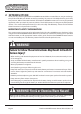
WARNING! Shock Hazard Keep Away From Children • Avoid moisture. Never expose unit to snow, water, etc. • Unit provides 230 VAC, treat the AC output socket the same as regular wall AC sockets at home. WARNING! Explosion Hazard • DO NOT use the Enerdrive ePOWER Inverter in the vicinity of flammable fumes or gases (such as gas bottles or petrol engines or battery compartments). • AVOID covering the ventilation openings. Always operate unit in an open area.
3 INSTALLATION WARNING! Shock Hazard Enerdrive recommends that all wiring be done by a certified technician or electrician to ensure adherence to the applicable electrical safety wiring regulations and installation codes. Failure to follow these instructions can damage the unit and could also result in personal injury or loss of life.
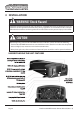
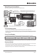
Material Prepare for Installation Typical Wiring block diagram of the Enerdrive ePOWER Inverter: Mains Power Only Battery Charger Mains or Inverter Power Example of how the Inverter's Transfer Switch can be incorporated into a vehicle/vessels electrical system. Top Air Conditioner Remote Hot Water Fuse / Breaker See Inverter Requirements Shore / Gen Selector Gen Set GPO Outlets This diagram is for a reference only. No Cables, Fuse/Breakers, Batteries, GPO are supplied with this unit.
Installing the Enerdrive ePOWER Inverter System WARNING! Electrical Shock Hazard The unit ‘On/Off’ switch does not disconnect the DC power from the battery. Use the DC Disconnect Switch or disconnect the DC input cables connection to disconnect the DC power from the battery before working on any circuits connected to the unit. Failure to follow these instructions can result in death or serious injury. ePOWER Inverter Installation: • Choose an appropriate mounting location.
DC Input and Grounding Cable: • All DC cables require insulated multi-strand low resistance cable. • The DC cables must be copper and must be rated 105º minimum Model Minimum Wire Size Recommended cable size between DC source and inverter 2000W Unit 70mm2 < 1.5m 2600W Unit 120mm <1.5m 2 CAUTION Use of smaller gauge cable or longer cable length may cause the inverter to shutdown under heavy load and may also melt the cable insulation and catch fire. This could result in death or serious injury.
1. 2. 3. 4. 5. 6. 7. Connect one end of the negative DC input cable to the ePOWER Inverter DC negative terminal. Connect the other end of the negative DC input cable to the battery negative or System side of the Shunt if a battery monitor is installed. Make sure the disconnect switch (battery switch), if fitted, is in the OFF position. Connect one end of the positive DC input cable to the ePOWER Inverter DC positive terminal.
Residual Current Device (RCD Safety Switch) This inverter is fitted with a Residual Current Device (RCD Safety switch as standard). The Residual Current Device (RCD) switch detects if there is an earth leakage fault and will automatically disconnect all output power sockets protecting the user from electrocution. Meets Australian Standards for AS4763 (portable inverters) and AS3001 (caravan installation) The inverter has a Mains Earth Neutral (M.E.
4. FEATURE SETTING To understand more about the unit features, read the following section and follow the instructions to make changes to the desired setting. Default Factory Setting: PS (Inverter): PS1 - inverter enabled in standby mode with load sense off AL (Alarm): AL1 - alarm enabled Sd (UV shutdown): SdL - Under voltage shutdown set to low setting Understanding the Unit Settings Inverter Setting PS0 Inverter is disabled, AC Output is getting the power from utility (AC Input) only.
Battery under-voltage setting is set to HIGH (setting to avoid battery over discharge when connected to car start battery) SdH Under-voltage alarm: ................................. 12.1 Vdc Under-voltage alarm recovery: ............... 12.3 Vdc Under-voltage shutdown: ........................ 11.8 Vdc Under-voltage shutdown recovery: ....... 12.6 Vdc Alarm Setting AL0 Fault and the warning audible alarm is disabled. The display panel only shows error code and the audible alarm will not sound.
5 UNIT OPERATION Auto Backup Mode (whatever “PS” setting except “PS0”): The unit is fully automatic. When utility power is available, the unit is running in AC By-Pass mode. AC output is supplied from the utility.
Green ‘12.5’ Battery/Inverter Mode. Inverter is running. Display shows battery voltage in DC volts Amber ‘0.80’ Battery/Inverter Mode. Inverter is running, Display shows output power in kW (800W as shown) Amber (solid) Amber (flashing) Battery (Inverter) Mode and AC Input is detected and unit will switch to ByPass mode within 20 seconds Red (solid) OFF E01-E12 Unit has shutdown.
Please note that there is a power drain of approx 700mA from the battery bank when the Inverter is running in AC By-Pass mode. In order to avoid draining down the battery bank, a battery charger with sufficient power is required to maintain the battery bank voltage. Estimate run time on different 12V Battery Bank Size AC Load 60AH 120AH 180AH 240AH 50 W 100 W 300AH 11 hrs. 22 hrs. 33 hrs. 44 hrs. 55 hrs. 5 hrs. 11.5 hrs. 17 hrs. 23 hrs. 29 hrs. 200 W 2.5 hrs. 5 hrs. 8 hrs. 11 hrs. 13.
6 TROUBLESHOOTING Understanding the Error Code Code Condition Corrective Action When unit is in Battery (Inverter) mode, Recharge the battery immediately and Input battery voltage is too low and AC restart unit. Make sure the battery is Output is shutdown. connected to the unit. E01 When unit is in By-Pass Mode the unit continues supplying AC-Output power. Check the battery is connected to the unit. Although the unit still provides AC Output power from Utility, recharge the battery ASAP.
To troubleshoot the unit, please note the error code displayed on the main unit and review “Understanding the Error Codes” in this section. Problem Possible Cause/Condition Solution The unit is turned off. No AC Output. All the LEDs and the display are off.
The unit is normal. The alarms indicate the battery voltage is low or the battery is not connected.
Make sure you are measuring the voltage directly at the DC-Input terminals of the unit so as to check the possible voltage drop between the battery posts and the unit input terminals Battery bank with high internal resistance, resulting in a voltage drop proportional to the DC current draw from the unit. The input battery under-voltage warning (“E05”) and/ or shutdown alarm (“E01”) occurs in advance even when the battery voltage seems to be OK Battery bank is getting discharged.
The display doesn’t work as expected (no display or showing “888”) and the operation of the unit may be affected The RCD trips as soon as the load is connected to either outlet port Loose contact or pin-out problems in the RJ12 detachable display panel cable A short (7”) RJ12 cable is used when the detachable display panel is mounted on the unit (factory default). Alternatively a long RJ12 cable is provided for installing the display panel up to 7.5m away.
7 SPECIFICATIONS Note: Specifications are subject to change without notice. Specifications: ePOWER True Sine Wave Series Inverter EN1120X EN1120X-24v EN1126X AC Output Power 2000W 2000W 2600W AC Output Current 8.7A 8.7A 11.3A AC Output Voltage 230 VAC / 50 Hz AC Output Waveform Sinewave (<3% THD) Nominal DC Input Voltage 12.5 VDC No Load battery draw < 1.5 ADC DC Input Voltage operating range 10.5 – 15.5 VDC 21.0 – 31.0 VDC Under Voltage Alarm 11.0 / 12.1 VDC 22.0 / 24.2 VDC 11.
8 WARRANTY Two Year Limited Warranty The limited warranty program is the only one that applies to this unit, and it sets forth all the responsibilities of Enerdrive. There is no other warranty, other than those described herein. Any implied warranty of merchantability of fitness for a particular purpose on this unit is limited in duration to the duration of this warranty.
APPENDIX I Setting Mode Flo Chart: Unit in normal operation 12.
APPENDIX II Detachable Display Panel Cable: The display panel is detachable and can be installed away from the unit, using the provided 7.5m RJ12 cable. You will need to remove the two screws indicated below. Even though the unit can operate with the cable plugged in whatever direction, we suggest plugging the end with the ferrite bead EMI/RFI filter into the main unit. Ferrite Bead Filter This end toward the main unit.
NOTES: Page 26 Enerdrive ePOWER Inverter Owners Manual (Rev. 1.
NOTES: www.enerdrive.com.
ENERDRIVE PTY LTD Unit 11, 1029 Manly Road Tingalpa, Queensland, Australia 4173 Ph: 1300 851 535 / Fax: 07 3390 6911 Email: sales@enerdrive.com.au Web: www.enerdrive.com.