
Manual


Enerdrive ePOWER Inverter Owners Manual (Rev. 1.0)Page 10
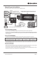
1.
Connect one end of the negative DC input cable to the ePOWER Inverter DC negative terminal.
Connect the other end of the negative DC input cable to the battery negative or System side of
the Shunt if a battery monitor is installed.
2. Make sure the disconnect switch (battery switch), if tted, is in the OFF position.
3.
Connect one end of the positive DC input cable to the ePOWER Inverter DC positive terminal.
Connect the other end of the positive DC input cable to one of the terminal of the Disconnect Switch.
4. Connect a DC input cable between the other terminal of the Disconnect Switch and one side of
the terminal of the fuse holder.
5. Connect a DC input cable between the other terminal of the fuse holder and the battery positive
terminal.
6. Install the selected fuse to the fuse holder.
7. Turn disconnect switch (battery switch), if tted, to the ON position.
AC Output Connections:
CAUTION
Please be sure that the AC Input source is not energized before making any Output connection
and that the DC disconnect switch is turned OFF.
Automatic AC Transfer Switch
This inverter is tted with an Automatic AC Transfer switch. This transfer switch seamlessly diverts AC
power from mains/generator supply and/or the inverter supply through the 16A IEC Output socket
that’s mounted on the side of the inverter. There are two IEC sockets, 1 x AC Inlet & 1 x AC Outlet that are
required to be hardwired to your on-board electrical system if you wish to use the transfer switch option.
When mains/generator power is applied to the AC Input IEC socket, the Auto Transfer Switch switches
this power through to the 16A IEC Output socket as well as the 10A 3pin GPO outlet mounted on the
front of the inverter.
When the inverter is operating as an “Inverter” both the IEC Output socket and 3pin GPO are supplied
from the battery to a maximum wattage output of the inverter.
When the inverter is operating with mains/generator power input, the maximum transfer wattage is
3500W (16A AC) for the IEC Output socket or 2400W (10A AC) for the 3pin GPO outlet.
To use the 16A IEC sockets, the unit is supplied with a separate male & female IEC plug as standard. These
plugs are designed to be hardwired by a qualied electrician to the AC distribution of the intended
installation.
AC Input Source and AC Branch Breaker:
• Standard AC Input wire is required for all the AC connections between the AC source & the AC Input
port, and the AC Output ports to load.
•
For 230V model and maximum By-Pass power rating, a minimum of 2.5mm2 AC wire is required. A 16A
branch circuit breaker is also required to connect between AC Input source and unit’s AC Input port.
Important: Follow the local electrical and/or building code when you connect the unit to any AC source.