
Manual


www.enerdrive.com.au Page 7
Material Prepare for Installation
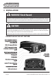
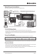
Typical Wiring block diagram of the Enerdrive ePOWER Inverter:
12v House Battery Bank
This diagram is for a reference only. No Cables, Fuse/Breakers, Batteries, GPO are supplied with this unit.
Local rules and regulations should be followed when installing this unit.
GPO Outlets
Fuse / Breaker
See Inverter Requirements
Top
Remote
Battery
Charger
Air
Conditioner
Hot Water
Shore /
Gen
Selector
Gen Set
Mains Power Only
Mains or Inverter Power
Example of how the Inverter's Transfer Switch can be
incorporated into a vehicle/vessels electrical system.
12V & 24V Battery Banks:
• The use of deep cycle battery is highly recommended for power inverter application.
• For battery size, you need to identify how much you will be using them between charges. Enerdrive
recommends you purchase as much battery capacity as possible. See more on Battery Run time and
Load in Section 4.
Fuse or Circuit Breaker:
• DC rated fuse or DC rated circuit breaker connected along the DC positive line is required.
2000W 24v Model 2000W 12v Model 2600W 12v Model
Fuse/Circuit Breaker Rating 150Adc 250Adc 350Adc
• For all applications, an over-current protective device needs to be installed within 17.8cm from the
battery positive terminals
Disconnect Switch:
• Select a Disconnect Switch with the same or higher the rating of the selected fuse or circuit breaker
from the above. Use ignition protected switches when required by local codes.
• The Disconnect Switch is used to disconnect the DC power between the ePOWER inverter and the
battery bank during service, maintenance or trouble shooting.