SOLAR CHARGE CONTROLLERS Owner’s Manual SMART AUTOMATIC 12/24 VOLT PWM SOLAR CONTROLLER 4 STAGE CHARGING EN43020 - 20A EN43030 - 30A
SOLAR CHARGE CONTROLLERS Please Keep This Manual For Future Reference For safe and optimum performance, the Enerdrive ePOWER Solar Charge Controller must be used properly. Carefully read and follow all instructions and guidelines in this manual and give special attention to the CAUTION and WARNING statements. Disclaimer While every precaution has been taken to ensure the accuracy of the contents of this guide, Enerdrive assumes no responsibility for errors or omissions.
Introduction The ePOWER 20 & 30 Amp Solar Charge Controllers are common positive PWM charge controllers with built in LCD display and USB ports. The multiple load control modes enable them to be widely used on caravans, camper trailers, boats, portable solar panels, commercial street signs etc. The ePOWER Solar Charge Controller range is built for the toughest Australian conditions using professional level components which have resulted in efficiency, increased reliability and performance.
SOLAR CHARGE CONTROLLERS IMPORTANT SAFETY INFORMATION This section contains important safety information for the Enerdrive ePOWER Solar Charge Controller. Each time, before using the Enerdrive ePOWER Solar Charge Controller, READ ALL instructions and cautionary markings on or provided with the controller, and all appropriate sections of this guide. The Enerdrive ePOWER Solar Charge Controller contains no user serviceable parts. Opening up the controller will void product warranty.
FIRE AND/OR CHEMICAL BURN HAZARD Page 5 www.enerdrive.com.
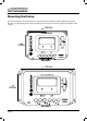
SOLAR CHARGE CONTROLLERS Mounting the Device The Solar Controller is best mounted on a vertical surface for maximum cooling efficiency. To mount the unit, use self-tapping screws and mount the unit via the four screw holes supplied and affix to a flat surface. 145mm 70mm EN43020 175mm 80mm EN43030 Page 6 www.enerdrive.com.
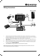
Wiring Connections Phone or Tablet Solar Controller Solar USB Charging Cable 3 Inverter 1. 2. 3. 4. 5. Fuse Load Fuse Breaker Battery Bank 12V/24V 2 1 Connect components to the charge controller in the sequence as shown above (1,2,3) and pay particular attention to the “+” and “-”. Please don’t insert the fuse or turn on the breaker during the installation. When disconnecting the system, the order will be reversed, (3,2,1).
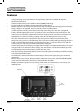
SOLAR CHARGE CONTROLLERS Features • • • • • • • • • • • • Page 8 4 Stage charging ensures the battery is charged to the optimum level (Bulk, Absorption, Equalisation and Float) Advanced MCU control pulse width modulated (PWM) technology Programmable for Gel, AGM and Conventional Flooded batteries Built in regulator to prevent your battery from being overcharged. Overcharging occurs when the charge voltage is unregulated.
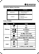
Operation: Battery Function Button MENU Button Function Browse through screens Setting parameter Load ON/OFF SET Button Clear error Enter into SET Mode Save data Status Display Page 9 www.enerdrive.com.
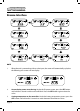
SOLAR CHARGE CONTROLLERS Browse Interface NOTE 1. When the unit is powered up with no solar input, the screen will automatically cycle, but the following two screens will not display. 2. Accumulative power zero clearing: Under the PV power screen, press the SET button and hold for 5 seconds and the value will blink. Press the SET button again to clear the value. 3.
Fault Indication Status Icon Description Battery over discharge Battery level shows empty, battery frame blink, fault icon blink Battery over voltage Battery level shows full, battery frame blink, fault icon blink Battery overheating Battery level shows current value, battery frame blink, fault icon blink Load failure 1. When the load current reaches 1.02–1.05 times 1.05–1.25 times, 1.25–1.35 times and 1.35–1.
SOLAR CHARGE CONTROLLERS LOAD MODE SETTING Operating Steps: Under the load mode setting screen, press the SET button and hold on for 5 seconds until the number begins flashing, then press the MENU button to set the parameter, then press the SET button to confirm. NOTE: Please set the Light ON/OFF, Test mode and Manual mode via Timer 1. Timer 2 will be disabled and display “2 n”.
Protection Protection Conditions Status PV Reverse Polarity When the battery is connected correctly, the PV Polarity can be reversed. The controller is not damaged Battery Reverse Polarity When the battery is not connecting, the Battery Polarity can be reversed.
SOLAR CHARGE CONTROLLERS Troubleshooting Faults Possible Reasons Troubleshooting PV array disconnection Cable connection is correct, LCD Screen not displayed 1). Battery voltage is lower than 9V 1). Please check the voltage of battery At least 9V is required to activate the controller 2).
Specifications Item EN43020 EN43030 Nominal system voltage Battery input voltage range 12/24 VDC 12/24 VDC 9V ~ 32V 9V ~ 32V Rated charge/discharge current Max. PV open circuit voltage 20A@55˚C 30A@55˚C 12V - 25VOC/24V - 50VOC Battery type Sealed (Default) / Gel/ Flooded Bulk/Absorption Charging Voltage Sealed: 14.4V/ Gel:14.2V/ Flooded 14.6V Equalize Charging Voltage Sealed: 14.4V/ Gel:14.2V/ Flooded 14.8V Float Charging Voltage Sealed/ Gel/ Flooded: 13.
SOLAR CHARGE CONTROLLERS Warranty Statement 2 Year Limited Warranty Our goods come with guarantees that cannot be excluded under the Australian Consumer Law. You are entitled to a replacement or refund for a major failure and for compensation for any other reasonably foreseeable loss or damage. You are also entitled to have the goods repaired or replaced if the goods fail to be of acceptable quality and the failure does not amount to a major failure.
If such a unit is returned more than 30 days but less than two years from the purchase date, Enerdrive will repair the unit or, at its option, replace it, free of charge. If the unit is repaired, new or reconditioned replacement parts may be used, at manufacturer’s option. A unit may be replaced with a new or reconditioned unit of the same or c omparable design. The repaired or replaced unit will then be warranted under these terms for the remainder of the warranty period.