
Manual
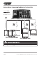

• Remove the DC compartment cover by removing the two
screws located on the top surface of the unit near the AC wiring
compartment.
• Keep the connection between the battery and the charger as short
as possible.
• Connect one end of the positive wire (red wire) to the Bank one of
charger positive terminal with torque 4.0 ~ 5.0 N-m and the other
end to the over current protection device, then the DC disconnect
device. Do not over tighten as this may result in damage to the
charger.
• Connect another wire from the DC disconnect device to the battery
bank.
• For systems with multi-battery banks: Follow the same instruction
as on Bank 1 and connect to Bank 2 & 3 accordingly.
• Prepare the negative wire (black wire) and connect to the negative
terminal of the charger.
• Connect the other end of the negative wire to all the negative
terminals of the battery bank(s) or the load side of a battery monitor
shunt if installed.
• Place the DC Compartment cover back to the original position and
secure the cover using the two screws provided.
Standard Temperature Sensor Connection
To install the temperature sensor, simply connect the RJ12 plug from the
sensor to the RJ12 Temperature Sensor Port located near the Interface
Port.
On the temperature sensor ends, simply connect the ring terminals to
the negative terminal of one of the battery banks.
Optional Remote Display Connection
• To install the optional Remote Display in a specic location, a 6 pin
Enerdrive ePOWER Battery Charger Owner’s Manual (Rev. 5.2) Dec 2015Page 18