USBird HAWK / FALCON / EAGLE8/A / MONO8 / FLEX8C AUDIO / VIDEO RECORDERS USERS MANUAL WINDOWS VERSION RELEASE 5.
TABLE OF CONTENTS SECTION 1 PAGE INTRODUCTION ……….………………………………….. 3 1.1 System Requirements 1.2 Installation 1.3 Run Program 1.4 Red LED 1.5 Powered USB Hub 2 SETUP ….……………………………………………………. 8 2.1 SETUP Settings - Descriptions and Functions 2.2 Set Timer 2.3 Erase Recorder 3 UTILITY ……………………………………………………….. 12 3.1 Setup Drives 3.2 Change Format Utility 3.3 Temp Button Sets Drive for AVI & WAV 3.4 View Recorder Revision Data 3.5 Clock Battery Expiration Date 3.6 Update Recorder Software 3.
9.1 PLAYER MAIN MENU BUTTONS 9.2 CREATE A JPEG 9.3 CREATE A SEGMENT 9.4 AVI 9.
SECTION - 1 INTRODUCTION The USBird support unit code was designed to be simple to use. To keep this manual down in size the obvious settings and displays will not be covered. The term "RECORDER" will be used when referring to the HAWK/4/8/8A, FALCON/4, EAGLE8 /A/B/C/D/E, FLEX8E, and all other ADS recorders with a built in USB port.
- USBird_Manual - a PDF copy of this manual 6- USBird_Install - a PDF instruction guide to load software. For new software installation follow this order: 1. Install USBird software. Refer to Appendix A. 2. Optional - Windows Media Player 7.1. If your computer does not correctly display AVI files, install new Windows Media Player. Refer to Appendix C.
1. In the Welcome to the Found New Hardware Wizard, select “Yes, this time only.” Refer to Figure 1.3.1 Hardware Wizard Figure 1.3.1 Hardware Wizard 2. Select “ Install the software automatically (Recommended)” Refer to Figure 1.3.2 Install Automatically Figure 1.3.2 Install Automatically 3. In the Completing the Found New Hardware Wizard select Finish. Refer to Figure 1.3.3 Complete Wizard Figure 1.3.
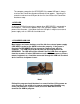
The computer recognizes the RECORDER if the same USB port is always used and the Found New Hardware Wizard will not appear. Attaching the recorder to a brand new USB port for the first time initiates the Found New Hardware setup. 1.4 RED LED A solid red LED (light) must always appear when RECORDER is connected to the computer. The red LED appears only if the USB port supplies sufficient power to the Recorder.
EAGLE8/A/B/C/D/E, MONO8, and FLEX8E use the USBird software. The video settings are disabled once the audio recorders are connected. Refer to Figure 15 Video Settings Figure 1-5 Video Settings IMPORTANT REMINDER!!! Always press the stop button or set the slide switch to OFF and remove batteries before you attach the RECORDER to the computer. If the RECORDER has not stopped recording properly, the recorder will begin recording again, once it is reconnected to the computer, and receives power.
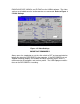
SECTION 2 SETUP The SETUP menu shown in Figure 2-1 appears on startup. Always select CONNECT RECORDER to read the settings of the attached RECORDER. The top right half of the screen displays the Current Recorder Settings of the RECORDER. Note the "Bad Chips" 0 of “X” for the HAWK, if you have any bad memory chips in the RECORDER please call ADS and make arrangements to have us repair the RECORDER at no cost to you.
The APPROXIMATE RECORDING TIME: displays the amount of recording time whether you have audio, video, or both. The RESOLUTION of the camera and VIDEO RATE greatly effect the approximate recording time. The HIGH and LOW Resolution are determined by which camera is currently connected. The HAWK automatically recognizes the camera type that is connected hence selecting “HIGH or LOW” is only for record time information. The Video Rate sets the frames per second. The maximum is 30 f/s and the minimum is1 f/s.
Figure 2.2.1 ENABLED / SET TIMERS 2. At the TIMER RECORDING START DATE / TIME the TIME is in military (24 Hour) format. Enter the date under TIMER RECORDING START DATE. A calendar appears. Enter the time in the TIME section. The TIME activates the recorder. Refer to Figure 2.2.2, Timer Mode Entry 3. Next enter the ”RECORD TIME,” the RECORD TIME keeps track of the record length. Once RECORD TIME has completed the RECORDER turns off. Refer to Figure 2.2.2, Timer Mode Entry 4.
Figure 2.2.2 TIMER MODE Entry Menu NOTE!! The unit automatically resets to MANUAL Mode after the data transfer. If you uncheck the “ENABLE box” and choose “APPLY CHANGES”, the unit will revert to Manual. 2.3 ERASE RECORDER The RECORDER data memory MUST always be erased after each use. The unit will not operate unless you have erased previous recordings, after complete and proper data transfer off all recordings. Depending on the unit, i.e.
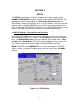
SECTION 3 UTILITY The UTILITY selection is covered next because the operator may need to define the computer disk drives for the USBird program and run maintenance programs for the RECORDER. If you received your computer from ADS the disk drives have been configured. Refer to Figure 3-1 for the UTILITY Menu. Figure 3-1 UTILITY Menu 3.1 SETUP DRIVES The SETUP DRIVES defines the different types of disk drives of the computer. The USBird does not automatically recognize the disk drive.
DragtoDisc software is C:\Program Files\Roxio\Easy CD Creator 7\DragtoDisc\DragtoDisc.exe. Refer to Appendix E-4 CHANGE FORMAT UTILITY If the drive is a re-writable MO (Magneto Optical) then the program will automatically use the Windows utility, therefore you do not need to define one. 3.3 TEMP Button Sets Drive for AVI & WAV The TEMP button selects the drive (hard disk, CD/DVD writer, thumb drive) where AVI and WAV files are stored after conversion. A folder is created and named HAWK_TEMP.
3.5 CLOCK BATTERY EXPIRATION The user may examine the internal Clock Battery expiration date from this menu. Every two years ADS will change the battery and re-test the recorder at no charge. 3.6 UPDATE RECORDER SOFTWARE This button will load the firmware that is on the hard disk into the RECORDER. This should be done as soon as possible when a new release is sent. Reloading the firmware does not erase the recorded data and parameters.
SECTION 4 TRANSFER To transfer the evidence to the archive media (CD/DVD) follow the steps outlined below: * Set the RECORDER to OFF and remove batteries. Use the USB cable provided by ADS to attach the RECORDER to the computer, 1. Select CONNECT RECORDER to read RECORDER settings and content. 2. Select TRANSFER and SELECT ALL, note the session information. Refer to Figure 4-1 Transfer “SELECT ALL” highlights all the sessions.
Figure 4-2 Select Storage Device After the user chooses DVD WR (DVD burner) or CD WR (CD burner) the CD/DVD Select displays the type of media and which sessions will be transferred. Selecting DVD 1 transfers all the sessions that will fit on the first DVD. The size of one DVD-R is 4.7 Giga bytes. DVD media has to be formatted. Refer to Figure 4-3 DVD 1 Figure 4-3 “DVD 1” A full HAWK/8 has 2 GBs of recording, transfers on multiple CD-Rs, typically 4.
will fit on the third CD. CD-R media has to be formatted first. Refer to Figure 4-4 CD3 FIGURE 4-4 “CD 3” 4. After the user views their selection in the CD/DVD Select, highlight DVD1 and select TRANSFER. Refer to Figure 4-6 TRANSFER BUTTON FIGURE 4-6 TRANSFER BUTTON The keyboard screen allows the user to input information regarding the data.
YOU SHOULD NOT USE SPECIAL CHARACTERS AND SPACES IN THE FILE NAME. 5. Enter descriptive information and select Enter. Refer to Figure 4-7 Keyboard 6. Data transfer begins. When the blue bars stop, transfer is completed. Refer to Figure 4-8 Transfer complete Figure 4-7 Keyboard The TRANSFERRING DONE displays when data transfer has completed. Select the CLOSE from CD/DVD Select button to go back to the USBird. Refer to Figure 4-8 Transfer Done 7. Playback the sessions through the PLAYBACK screen.
4.1 Definitions of the Status Abbreviations On the Transfer and Playback screens the STATUS of each session are displayed. Each abbreviation TR, FE, LB, and PF have their own definition. Refer to Figure 4-9 STATUS Figure 4-9 STATUS TR = Transferred session complete The chosen session has transferred properly. FE = Forced Ending The session closed in order to fit on one CD MEDIA. One Forced Ending fills one CD-R. You can select all of the sessions between 2 FE tagged files to transfer to 1 CD.
4.2 FORMAT CD / DVD WARNING!!! For EVIDENCE you should use a “GOLD” CD/ DVD because cheap media may loose data over time. We recommend “MITSUI GOLD”. 1. Select FORMAT button from the Transfer screen. Refer to Figure 4.2.1 SELECT FORMAT 2. Select the drive letter for burner and select FORMAT. Refer to Figure 4.2.2 DRIVE LETTER Figure 4.2.1 SELECT FORMAT Figure 4.2.2 DRIVE LETTER 3. The Roxio’s Drag to Disc interface appears. Refer to Figure 4.2.3 DRAG TO DISC INTERFACE 4.
Figure 4.2.3 DRAG TO DISC INTERFACE Figure 4.2.4 FORMATDISC 5. Enter Volume Label, which will be the name given to the CD and select OK. Refer to Figure 4.2.5 VOLUME LABEL Figure 4.2.5 VOLUME LABEL 6. After Format is complete, the Drag to Disc icon will appear with the disk name. Refer to Figure 4.2.6 ICON Figure 4.2.
4.3 EJECT THE CD / DVD 1. Select EJECT button. Refer to Figure 4.3.1 SELECT BUTTON Figure 4.3.1 SELECT BUTTON 2. Select the DRIVE letter and select EJECT. Refer to Figure 4.3.2 DRIVE LETTER Figure 4.3.2 DRIVE LETTER 3. Check the boxes of all the three options. Refer to Figure 4.3.3 EJECT OPTIONS 4. Select the EJECT button. Refer to Figure 4.3.
FIGURE 4.3.3 EJECT OPTIONS 4.4 COPY Recording from Hard Drive to CD/DVD The numbers in the diagram correspond to the direction number. 1. Format blank Media. (CD or DVD) Refer to Section 4.2 FORMAT CD / DVD 2. Go to PLAYBACK Refer to Figure 4.4.1 PLAYBACK SCREEN 3. At Play From select the storage device the recordings are archived. Refer to Figure 4.4.1 PLAYBACK SCREEN Figure 4.4.1 PLAYBACK SCREEN In most cases the letter “C” designates the hard drive.
Multiple recordings can be transferred together, for example sessions numbered 4,5,and 6 can be copied together since they are in sequential order. IF you wanted to copy sessions 1 and 6 you have to transfer them one at a time. 5. Select the COPY button Refer Figure 4.4.2 Select Session and Copy Figure 4.4.2 Select Session and Copy 6.In the Select Destination Drive Screen choose the CD/DVD burner. Refer Figure 4.4.3 Select Destination Drive Figure 4.4.3 Select Destination Drive 7.
Figure 4.4.4 Copy in Progress 8. Once the Copy Complete is displayed, check to make sure the recording plays back in the PLAYBACK Menu. Refer to Figure 4.4.5 Copy Complete Figure 4.4.5 Copy Complete 9. Eject and Finalize the CD/DVD through the DragtoDisc program. Refer to Section 4.
SECTION 5 PLAYBACK In order to initiate playing video / audio perform the steps outlined below: 1. Select the PLAYBACK button located on the top row. 2. Select the “Source” drive, C, D, E etc in PLAY FROM 3. Select File and Session(s) you desire to listen and watch 4. Select Play button. Refer to Figure 5-1, Press PLAY Figure 5-1 Press PLAY Once you choose the file, it will be converted to MJPEG and played through the USBirdPlayer.
Figure 5-2 “USBird Player” Menu . Most of the controls are obvious, Windows Media Player Menu. To play from any time, just place the mouse on the “white box” on the time bar and hold the left mouse button down. Drag the arrow to when you want to play and release the mouse button start playing. 5.1 Definitions of PLAYBACK Controls 1. The SETUP button configures the disk drives of the computer. 2. The PLAY FROM selects the storage device sessions are stored in. 3.
6. The EJECT button calls the DragToDisc program which finalizes and ejects the CD/DVD 7. The FORMAT button calls the DragToDisc program, which prepares a blank CD/DVD for data transfer. 8. The COPY button transfer files from different storage devices such as hard disk to CD/DVD or CD/DVD to hard disk. 9. The DELETE button removes files from the hard drive, select the file name of the recording. The removed files do not go to the recycle bin. Delete cannot delete files from a closed CD/DVD. 10.
PLAY RATE can be adjusted, for example if a recording was captured at 1 frame per second you can playback the recording at 30 frames per second for a faster playback. Go to the PLAY RATE meter and move the bar. Refer to Figure 5-4 PLAY RATE Figure 5-4 PLAY RATE The PLAYBACK window can fit the entire screen by removing the PLAYER graphical interface. This is used when the recording is made into an analog copy such as VHS tape. Right click on the PLAYBACK screen and select FULL SCREEN.
Analog audio can be made from the USBird recording. First attach an audio tape recording device to the sound card. Use the audio output of the sound card, usually the green connector. At the PLAYBACK screen check the box labeled ANALOG COPY. The Select screen appears. The select screen allows the user to choose an audiotape length. After you choose the TAPE LENGTH the audio will play. You should hit the record button on the audiotape device.
DATE AND TIME from Windows Media Player The running time and the date of the AVI recording can be displayed through Windows Media Player by selecting View, Now Playing, Tools, Caption. The date and time of the recording will be displayed at the bottom left of the playback screen.
SECTION - 6 HAWK4/8/A / FALCON/4 EAGLE8/A RECORDERS HAWK The HAWK line of recorders can perform both video and or audio recording. The record time is 30 f/s=1.7 HR; 15F/S=3 HR; 5 f/s-8 HR; 1 F/S=17 HR. The HAWK memory expansion cards (up to a total of 8) can be added to the HAWK for longer-term recordings. Each HAWK memory card adds 3 hours of lowresolution recording at 15 f/s. The HAWK2 has 4 Gigabytes of memory while the HAWK4 has 8 Gigabytes.
and stop buttons. The HAWK8/A does not have the local audio playback controls. The HAWK8/A uses the black slide switch to activate the recorder into record mode. The mini USB port on the HAWK8/A is different from the HAWK/4. The new generation HAWK4 uses the slide switch and new mini USB port. Refer to Figure 6-2 The HAWK8/A Figure 6- 2 The HAWK8/A EAGLE8/A The EAGLE 8/A is an audio only recording device.
FALCON/2 The FALCON is the next generation audio / video recording device. The FALCON is a slimmer version of the HAWK with more memory. The advantages of the FALCON are you can remove the recorder from the aluminum shell in order to place the recorder in objects where size makes a difference. The FALCON2/4 memory is 4 Gigabytes, which gives you a 4 hour recording at 30 fps at high resolution The FALCON uses a rechargeable lithium battery.
BATTERY Installation The HAWK uses two 1.5 v, "AA" batteries for operation. The batteries are installed series providing 3 volts. The HAWK8/A uses 2 and 4 “AAA” batteries. Please note the label in the bottom of the unit for proper battery installation. Two "AA" Alkaline batteries will last for 3.5 – 4 hours, while two “AA” Photo Lithium cells will last for 7.5 - 8 hours. You should not mix battery technology.
If the battery is low then the LED will flash ON and OFF slowly. No red or green LED present the record is not recording. NOTE! If the low battery indicator is flashing, turn the unit “OFF” replace the cells and turn the unit ON or “RCD” again. The computer will display the fact that the “last recording” was stopped short because of a low battery condition. The green "LED", further back, will be ON when the unit is in playback. In later software releases the LED will follow the playback audio levels.
CAMERA CIF CIF VGA VGA CAMERA RESOLUTION COLOR LOW RESOLUTION B/W LOW RESOLUTION COLOR HIGH RESOLUTION B/W HIGH RESOLUTION COLOR STRIPES NONE RED YELLOW YELLOW/RED MICROPHONE The HAWK/EAGLE8 and FALCON can use its stereo internal or external microphones. If the external microphone is plugged in it is automatically selected for use. The Left and Right microphone position is engraved on the chassis. The internal microphone is factory set for 6 dB more sensitivity, over the external microphone.
Next Generation: Our next generation recorders such as the HAWK/4, HAWK8, FALCON/4 use a black switch that slides into designated modes "ON" and "OFF If the remote record switch is attached to the RECORDER it must be used for ON/OFF control. When the red slide switch is slid to the “ON” position a black dot appears and the recorder begins recording. For special applications, ADS also makes a set of external microphones without the external ON/OFF switch.
The playback function uses all 4 switches. NOTE that you must be in the OFF state to re-enter the record mode. The REW and FWD switches have different meaning when in PLAY or PAUSE. Note that “playback” does not erase any data. Once you are finished with local “playback”, you may continue recording from where you left off by first turning the RECORDER “off” then pressing RCD. The HAWK8/A and FALCON4 do not have PLAYBACK capability.
One Forced Session One Forced Session Full Recording Length 30 f/s 15 f/s 10 f/s 5 f/s 1 f/s CIF (LOW) 22 minutes 42 minutes 60 minutes 105 minutes 258 minutes VGA (HIGH) 14 minutes 27 minutes 40 minutes 73 minutes 212 minutes CIF (LOW) 88 minutes 168 minutes 240 minutes 420 minutes 1032 minutes VGA (HIGH) 56 minutes 108 minutes 160 minutes 292 minutes 848 minutes RECORDING TIME AND BATTERY LIFE WITH VGA CAMERA AND AUDIO ON Battery Duracell Energizer 1 f/s 851 min 151 min LB 5 f/s 293 min 138 min LB
Figure 6-4 HAWK with button descriptions The Micro Cams records at 640X 480 pixels. (High Resolution) MICRO CAMS The SXGA camera records at 1290 x 960 resolution at 1.3 megapixel. The SXGA is mainly used in stationary applications for example, a pole camera.
The Low Light Cameras work well in environment where light is a limited resource.
SECTION 7 "MONO8" RECORDER Figure 7-1 MONO8 The MONO8 audio recorder captures stereo for 10 hours or mono for 20 hours. Note that the pager is fully functional with the exception of the vibrator function. The MONO8 has an Officer Safety Transmitter (OSRFT) option which transmits the audio continuously for up to 6 + hours while recording with the “L91” Lithium battery. When the MONO8 is not transmitting, an ordinary Alkaline “AA” will last for 10+ hours.
SECTION 8 FLEX8F The FLEX8F is our most covert recorder. The solid-state electronics built on an untra-thin form factor assures inconspicuous evidence recording in highly transportable packages. Data is transferred to any PC via a Universal Serial Bus (USB). Standard audio hardware commonly found on most PCs may be used for data playback. User software running under Windows 98/2000/XP/VISTA® will cut CD media for archive, and can also create audio CDs which can be played on any CD player.
SECTION 9 PLAYER Program The “PLAYER” is similar to our FBPLAYER used on the earlier EAGLE 2 and 4 line. The PLAYER plays audio and video files from the recorders however the PLAYER cannot change the settings of the RECORDER. The PLAYER code resides on all evidence CDs inside the HAWK directory. The PLAYER can execute on any PC and uses the PC’s Sound Blaster for audio output. To run PLAYER simply double click on the ICON located on the CD/DVD under HAWK/Player.exe . If you are using USBIrd software 2.
2. The PLAY button, once sessions are chose the PLAY button to go into the PLAY screen. 3. The AVI button converts audio/video recordings into AVI files. 4. The WAV button converts audio recordings into wav files 5. The EJECT button calls the DragToDisc program which finalizes and ejects the CD\DVD. 6. The FORMAT button calls the DragToDisc program which prepares a blank CD/DVD for data transfer . 7.
5. The IMAGE button extracts a picture frame from the recording 6. The session volume can be adjusted through the AUDIO L and R channel scroll bars. 7. The PLAY RATE adjusts the frames per second of playback. 8. The PLAY button begins audio and video playback. 9. The PAUSE button stops the playback, selecting the PLAY button resumes the playback. 10. The REW button advances the video recording back 1 frame. 11. The FF button advances the video recording forward 1 frame. Figure Player Playback Screen 9.1.
Figure 9.2.1 Select IMAGE b. Next select the PAUSE button. Refer to Figure 9.2.1 Select IMAGE c. Select the IMAGE button. Refer to Figure 9.2.2 IMAGE Button Figure 9.2.
d. In the SAVE AS screen select the location where to save the JPEG (use the down arrow to navigate through the folders) and input a name for the JPEG in the File name. Refer to Figure 9.2. 3 Save As Screen e. Select Save. Refer to Figure 9.2. 3 Save As Screen Figure 9.2. 3 Save As Screen f. Retrieve the JPEG for viewing. Refer to Figure 9.2.4 JPEG Figure 9.2.4 JPEG 9.3 CREATE A SEGMENT The USBird and Player program have the capability of creating SEGMENTS.
into its own individual session. The SEGMENT is created in the PLAYBACK screen. 1. Create the segment by using the scroll bar. Find the beginning of the SEGMENT and select SET. Refer to Figure 9.3.1 Start of SEGMENT Figure 9.3.1 Start of SEGMENT 2. Find the end of the SEGMENT select SET. Refer to Figure 9.3.
Figure 9.3.2 End of SEGMENT 3. Select the SEGMENT button. Refer to Figure 9.3.3 SEGMENT Button Figure 9.3.3 SEGMENT Button 10. In the CaseIDForm screen the SEGMENT is designated by the SG followed by the original file name and session number. The FILE NAME can be renamed. Refer to Figure 9.3.4 CaseIDForm 11. Select OK. Refer to Figure 9.3.4 CaseIDForm Figure 9.3.4 CaseIDForm The CLEAR button removes the previous bookmark from the scroll bar.
common user friendly format. An AVI file can be converted to the MJPEG2 format which can be played back on a standard DVD player. AVIs can also be generated from the USBird Program in the Playback screen. In this demonstration the AVI will be made from the PLAYER program. Figure 9.4.1 AVI File Menu Make “ .AVI” Files The numbers corresponds to the direction number. 1. From the PLAYER PROGRAM, Select the drive where sessions are stored in PLAY FROM. Refer to Figure 9.4.1 AVI FILE Menu 2.
5. Insert a blank CD\DVD in the CD\DVD-WRITER and select FORMAT. Format the CD using the DragToDisc software. Refer to Section 4.1 Format CD/DVD 6. Select the AVI under CONTENT 7. Select COPY, the AVI file is copied from Hawk_Temp to the CD/DVD. 8. Select EJECT and close out the CD Figure 9.4.2 AVI Conversion SCREEN GENERATE AVI FOR DATA DVD creates AVIs stored on DVD media. GENERATE SILENT AVI will create a file with video and no audio. A WAV file can be created from an audio/video recording.
9.5 WAV A WAV file is created for other programs that recognize the WAV file format such as WINDOWS MEDIA PLAYER. We covert our proprietary audio format to a user-friendly format. WAV files can also be generated from the USBird Program in the Playback screen. In this demonstration the AVI will be made from the PLAYER program. The numbers corresponds to the direction number. Figure 9.5.1 WAV File Menu Make “ .WAV” Files 1. From the PLAYER PROGRAM, Select the drive where sessions are stored in PLAY FROM. 2.
A music CD can hold about 70 minutes of audio recording. If you have a two hour recording two CDs are needed. The WAV files are converted and written to the Hawk_Temp Folder. The user chooses where the Hawk_Temp Folder is stored. Refer to Figure 7-5 WAV CONVERSION SCREEN 5. Insert a blank CD\DVD in the CD\DVD-WRITER and select FORMAT. Format the CD using the DragToDisc software. Refer to Section 4.1 Format CD/DVD Refer to Figure 9.5.2 WAV CONVERSION SCREEN 6. Select the WAV under CONTENT, Refer to Figure 9.
APPENDIX - A USBird SOFTWARE INSTALLATION To install/update the resident code from CD. 1. Remove existing software from the CONTROL PANEL/ ADD REMOVE PROGRAMS .2. Go to USBird folder and select ‘Setup.exe’. 10. In the Welcome screen, select next. 11. In the Choose destination location, select next. 12. In the Select Program Folder, select next. Start Copying files begins. 13. Drag out USBird short cut to Desktop. 14.
APPENDIX – B MJPEG CODEC Installing MJPEG If the video can not playback install the MJPEG codec. MJPEG Codec compresses the Hawk File so it can be played back through Windows Media Player. 1. Go to the MJPG_CODEC Folder. 2. Select LEAD MCMP_MJPEGCodec.exe. Figure B - Password 3. In the Lead MCMP_MJPEG Codec – Password type “showme” and select continue. Refer to Figure B - Password 4. File extraction begins. 5. In the Lead MCMP_MJPEG Codec with Free Converter screen select next. 6.
APPENDIX - C WINDOWS MEDIA PLAYER Installing Windows Media Player 7.1 If your computer does not correctly display AVI files install new Windows Media Player 7.1. 1. 2. 3. 4. 5. 6. 7. 8. Go to My Computer and go to USBIRD CD. Select mp71.exe In the Windows Media Player 7.1 Setup select Yes. In the License agreement, select Yes and file extraction begins. In the Windows Media Component Setup select next. Check the box, ‘I have read the Privacy Statement’ select next.
APPENDIX - D UPDATE BINARY CODE How to update HAWK Binary Code 1. Select Utility button. 2. Select UPDATE RECORDER SOFTWARE. Figure D-1 UPDATE RECORDER SOFTWARE 3. In the Confirm box select Yes.
Do not unplug the recorder while it is updating the binary code, this can cause malfunction in the Hawk. Code update takes approximately 40 seconds. 4. After binary code update is complete, select OK at the CODE UPDATED box. Refer to figure D-3 CODE UPDATED BOX. 5. Binary code update is successful when “HEX CODE LOAD DONE” is displayed. Refer to figure D-4 HEX CODE LOAD DONE SCREEN Figure D-3 CODE UPDATED BOX Figure D-4 HEX CODE LOAD DONE SCREEN 6. Disconnect RECORDER from USB cable for 10 seconds. 7.
APPENDIX – E SETUP DRIVES 1. Select UTILITY, and select SETUP DRIVES. Refer to Figure E-1 Setup Drives Figure E-1 Setup Drives 2. In Setup Drives select ADD Refer to Figure E-2 Setup Drives Figure E-2 Setup Drives 3. Select drive with corresponding letter, choose TYPE and select OK.
Figure E-3 Add Drives 4. If the space is blank, press Change Format Utility button, to select the format program. The path for ROXIO 5 is C:\Program Files\Adaptec\Easy CD Creator\DirectCD\directcd.exe. The path for ROXIO 6 is C:\Program Files\Roxio\Easy CD Creator 6\DragtoDisc\DragtoDisc.exe. Refer to Figure E-4 CHANGE FORMAT UTILITY Figure E-4 CHANGE FORMAT UTILITY 5. The new drive will be added, select OK.
Figure E-5 New Drive Added 6. Now you can view the drives that were added.
APPENDIX - F BATTERY ORIENTATION Proper battery placement is necessary in order for the recorder to function correctly. Use the battery diagram as a guide. NEVER remove batteries when device is recording. Figure G-1 Battery Diagram Figure G-2 Battery Installation Always use a fresh battery when using the recorder and follow correct battery installation.
APPENDIX - G ADS SOFTWARE CONFIGURATIONS This message was written to clear up some confusion that may exists on the various software and hardware releases that are out in the field. FBIRDWIN 3.5 (and 3.X) is used with desktops and PDR (not PDR2) stations. This software will not run on Windows 2000, and Windows XP. USBI 1.91 (and 1.0x) is used with the black USB boxes as well as the PCI card version.
APPENDIX - H TROUBLE SHOOTING Most problems can be solved by referring to the USBIRD MANUAL. Before you use the recorder, make sure memory has been erased. If you press the record button and see three blinking lights you must erase the recorder memory. The memory cannot not be overwritten, after you completely erase the memory the recorder will begin recording. Always test the recorder before you deploy it. Make sure audio and video are working properly.
APPENDIX – I Micro Cam Installation Mounting a MICROCAM into the concealment is made easy by the items below. The three items are shipped with the MICROCAMS. The items include, a drill bit, a center punch, and camera bezel or frame. MICROCAM Concealment Kit 1. Choose an item 2. Make sure the surface lays flat and does not distort while moving. 3. Place the center punch and camera bezel flat on the item. 4. Mark the edges of the camera bezel for easy alignment.
Center Punch and Camera Bezel Drill Bit 5. Place the drill bit inside the center punch. The center punch and camera bezel align the camera hole. 6. Once the camera hole is made remove the drill bit and center punch. 7. Replace the center punch with the MICROCAM. 8. Glue down and around the camera bezel; make sure the camera lens is not obstructed.