Veritas ™ OWNERS MANUAL Printed in Canada 7AI//EV201
WELCOME TO MUSICAL TRUTH ™ The new ENERGY® Veritas™ Series Congratulations on your purchase of the new Veritas™ Series speakers from ENERGY® Loudspeakers. The proprietary technology in the Veritas™ series has taken years for the engineering division to design and implement into this groundbreaking new speaker series. Veritas™ follows the lead of its predecessors by adhering to four main goals.
OWNERS MANUAL VERITAS ™ Table of Contents Welcome to Musical Truth™ 3 Table of Contents 4 Break in Procedures 5 Set-Up Basics 5 Advanced Set Up 5 Positioning the Front Speakers Advanced Set Up 5 6 Placement of the Center Channel V2.0C 6 Placement of the Rear Channel V2.0R Speakers 6 Side Position 6 Rear Position 6 Corner Position 6 ™ Proper Usage of the Veritas Stand for V2.1 and V2.
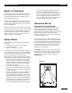
OWNERS MANUAL Break in Procedures It is VITAL that your new Veritas™ speakers be allowed to break In properly before you perform any precise set up procedures, system adjustments, and before you play them at higher volume levels. The best method of performing the break in is to play a full range musical passage at a moderate level as long as possible. Utilizing the repeat function on your CD or DVD player can assist greatly. VERITAS ™ the position of the listeners.
OWNERS MANUAL Advanced Set Up PLACEMENT OF THE CENTER CHANNEL V2.0C The center channel needs to be placed either above or below the TV monitor, but as close to the TV as possible. The center channel carries dialogue information which should sound like it is emanating from the center of the TV. If using a Rear Projection Television, then above is probably your only choice. If you have a front projection system, than you have alternate choices of either stand mounting, or placement on furniture, etc.
OWNERS MANUAL VERITAS ™ Proper Usage of the Veritas™ Stand for V2.1 and V2.2 Models The Veritas™ Stand has been purpose built not only to improve the looks of the Veritas™ bookshelf models V2.1 and V2.2, but also to place the speakers at the optimum height. The Veritas™ speakers incorporate inserts into the speakers' bottom, to allow physically attaching the speaker to the stand for enhanced safety. Please follow the instructions in this order.
OWNERS MANUAL VERITAS ™ Connection Instructions The Connections for the Veritas™ Series speakers are quite similar to any standard speaker with bi-wire/ bi-amp options. There are 4 Gold Plated Connectors on the rear of the speaker enclosure, and although they look unique, they are traditional in function. NOTE: Before starting, remove the gold straps, which connect the top and bottom set of terminals.
OWNERS MANUAL 2) 3) VERITAS ™ Next, connect the second cable, from the amplifiers other channel to the lower set of terminals again ensuring a tight connection. Repeat Steps 1 and 2 for the second loudspeaker using the second amplifier. See Figure 5. NOTE: Notice the upper and lower terminals accept the wire from a different angle, this is to simplify the connection process by making access easier, and to improve cosmetics by allowing easier “dressing” of the cables.
OWNERS MANUAL Adjusting the V2.0R Rear Channel speaker The exclusive and patented “Soundfield Management” System allows adjustment of the surround field in different room environments, to compensate for different direct to reflected sound ratios. The controls permit adjustment of the soundfield type, and the relative level of the side firing drivers compared to the front drivers. In a perfect world, all of the 5 speakers in a home theater would be the same distance from the listener.
OWNERS MANUAL VERITAS ™ HOW TO SET UP THE CONTROLS The following chart (Diagram “B”) will explain how to set up the controls on the Soundfield Management System. But follow these instructions first. 1) The first thing you must do is measure two distances. First measure the distance between the listening position and one of the front speakers (D1 on Diagram “A”), then measure the distance between the listening position and the rear speakers, (D2 on Diagram “A”).
Tweeter: 1.8kHz and > Woofer: ~ to 1.8kHz Operating Range H - 15” / 38cm D - 12-1/2” / 31.7cm W - 8-3/4” / 22cm 55lbs / 24.75kg (Dual) Cherry Veneer w/ Black HG Black w/ Black 2 Silver Cone Isolators Rubber Bumpers Shipping Weight Cabinet Finishes Accessories 1-6-1/2” Linear Tandem Drive Woofer Dimensions Components 1” Aluminum Dome Tweeter 1.8kHz Crossover Points V2.3 Tweeter: 2.0kHz and > Midrange: 550Hz-2.0kHz Woofer 2: ~ to 550Hz Woofer 1: ~ to 300Hz 300Hz, 550Hz, 2.
OWNERS MANUAL Safety Concerns IMPORTANT: Please retain the carton and packing materials for this ENERGY® Veritas™ product to protect it in the event you ever need to transport the unit for any reason. Product received damaged at a service center that has been shipped by the end user in other than the original packaging, will be repaired, refurbished and properly packaged for return shipment at the end user's expense.
WARRANTY Limited Warranty Policy in the United States and Canada ENERGY® LOUDSPEAKERS warrants this product to the retail purchaser against any failure resulting from original manufacturing defects in workmanship or materials. The warranty is in effect for a period of 5 years from date of purchase from an authorized ENERGY® dealer and is valid only if the original dated bill of sale is presented when service is required.
Energy Loudspeakers, a Division of Audio Products International Corp. 3641 McNicoll Avenue, Scarborough, Ontario, Canada M1X 1G5 416-321-1800 Fax 416-321-1500 www.energy-speakers.