INSTALLATION, OPERATING AND SERVICE INSTRUCTIONS CL™ SERIES CAST IRON OIL-FIRED BOILER As an ENERGY STAR® Partner, New Yorker Boiler Co., Inc. has determined that the CL3-091, CL3-105, CL4-126 and CL5-168 water boilers meet the ENERGY STAR® guidelines for Energy efficiency established by the United States Environmental Protection Agency (EPA). F o r s e rvi c e o r re p a i rs to b o i le r, c a ll yo ur he a ti ng c o ntra c to r.
IMPORTANT INFORMATION - PLEASE READ THIS PAGE CAREFULLY 1. Read and understand all instructions, including all those contained in component manufacturers manuals which are provided with the appliance before installing, starting-up, operating, maintaining or servicing this appliance. Keep this manual and literature in legible condition and posted near appliance for reference by owner and service technician. 2.
WARNING This boiler is suitable for installation on combustible flooring. Do not install boiler on carpeting. Installation is not complete unless a pressure relief valve is installed into the tapping located on top left corner of rear section - See Piping and Trim Sections of this manual for details. This boiler is designed to burn No. 2 fuel oil only. Do not use gasoline, crankcase drainings, or any oil containing gasoline. Never burn garbage or paper in this boiler. Do not convert to any solid fuel (i.e.
Table of Contents I. General Information..................................... 4 III. Indirect Water Heater Piping..................... 23 Trouble Shooting Carlin 40200.............................................. 36 Riello 40 Series........................................ 36 IV. Operating & Service Instructions............. 24 VII. Repair Parts..............................................37 V. Maintenance and Service Instructions..... 30 VIII. Appendix Low Water Cut Off..................
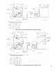
Figure 1A: CL3 Thru CL5 Water Boiler Less Tankless Heater Figure 1B: CL3 Thru CL5 Water Boiler With Tankless Heater
Figure 1C: CL3 Thru CL5 Steam Boiler with or without Tankless Heater Figure 1D: CL3 thru CL5 Steam Boiler with McDonnell & Miller PS-801 Low Water Cut-Off, Riello Burner TABLE 1: DIMENSIONAL DATA (See figures 1a thru 1c) Boiler Model Dimensions "A" "B" "C" Minimum Chimney Size Rectangular Round Approx. Water Content - Gallons Heat Transfer Surface Area - Sq. Ft. CL3 17-3/8" 8-1/4" 5-7/8" 8" x 8" x 15' 6" x 15' 16 14.33 CL4 22-3/8" 10-7/8" 6-7/8" 8" x 8" x 15' 7" x 15' 20 20.
table 2: rating data Burner Capacity Boiler Model No. * DOE Heating Capacity GPH MBH CL3-091(W) 0.65 91 Minimum Chimney Requirements I=B=R NET Ratings AFUE % Water MBH Steam MBH Water MBH Steam MBH Steam Sq. Ft. Round In. Dia. Rectangle In. x In. Height Ft. 80 --- 70 --- --- 6 8x8 15 Water Steam 86.0 --- CL3-091(S) 0.65 91 --- 78 --- 56 233 6 8x8 15 --- 84.1 CL3-105(W) 0.75 105 91 --- 79 --- --- 6 8x8 15 85.1 --- CL3-105(S) 0.
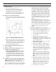
II. Installation Instructions 1. PACKAGED CL™ Series boilers are shipped with the highest input oil nozzle installed in the burner. Oil nozzles for lower firing rates are shipped loose for the CL3 through CL5 models, attached to the burner. Select the proper oil nozzle for the installation. The lower input nozzle will provide greater boiler efficiency. However, boiler output will be reduced. Refer to Table 2 for firing rates.
l. Inspect Beckett head setting on left side of burner by insuring the blue line MD(V1) or the line on the label MB(L1) are aligned, readjust if necessary. check the settings and to change the nozzle to a lower firing rate: a. Installation/Removal of Drawer Assembly, refer to Figure 4. m. Tighten knurled nut. n. Swing igniter closed, rotate tabs and tighten two (2) igniter screws. o. Replace burner cover and tighten burner cover knobs. 3.
ii. Remove existing nozzle from nozzle adapter. iii. Insert the proper NOZZLE into NOZZLE ADAPTER and tighten securely (Do not cover tighten). iv. Replace adapter, with nozzle installed, into drawer assembly and secure with screw (1). c. Inspect and measure burner electrodes. Refer to Figure 6 for the proper electrode settings. Figure 6: Electrode Setting d. Re-install Drawer Assembly into Combustion Head per Step 4a above. e.
Figure 9: Recommended Boiler Piping for Series Loop Hot Water System NOTE: Vertical piping will prevent door from opening fully for service and cleaning of boiler. 2. Thread relief valve onto factory installed ¾" NPT x 7¼" nipple located in left rear corner on top of boiler as shown in Figures 1A and 1B. Valve spindle must be in vertical position. Tighten with wrench. Pipe discharge as shown in Figure 9.
2. Install ¾" drain valve in wet return piping as shown in Figure 11. 3. On boilers with rear tankless heater, factory wired L4006A Aquastat Heater Control was not installed in heater. Locate ¾" NPT Immersion Well, apply sealant and thread into ¾" NPT tapping on heater. Apply heat transfer paste (not furnished) to control bulb and insert bulb into immersion well. Tighten clamping screws to secure control to immersion well.
2. WATER BOILER a. For Forced Circulation HOT WATER HEATING. See Figure 9. Consult I=B=R Installation and Piping Guide No. 200. b. Use a boiler water bypass if the boiler is to be operated in a system which has a large volume or excessive radiation where low boiler water temperature may be encountered (i.e. converted gravity circulation system, etc.). Install a pipe tee between the circulator and boiler return along with a second tee in the supply piping as shown in Figure 9.
I. CONNECT TANKLESS HEATER PIPING AS SHOWN IN Figure 12. See Table 3 for Tankless Heater Ratings. addition, savings of hot water will be achieved since the user will not waste as much hot water while seeking water temperature to his liking. Higher temperature hot water required by dishwashers and automatic washers is possible by piping the hot water from the heater prior to entering the mixing valve.
Figure 13 Recommended Smokepipe Arrangement and Chimney Requirements the heat loss of the home has been reduced. This requires less fuel to be burned and sends less heat up the chimney. A new boiler probably has a higher efficiency than the boiler being replaced. That probably means that the stack temperature from the new boiler will be lower than that from the old boiler and with less room air being drawn up the chimney to dilute the stack gases.
K. FUEL UNITS AND OIL LINES SINGLE-PIPE OIL LINES Standard burners are provided with single-stage 3450 rpm fuel units with the by-pass plug removed for single-pipe installations. The single-stage fuel unit may be installed single-pipe with gravity feed or lift. Maximum allowable lift is 8 feet. See Figure 15. TWO-PIPE OIL LINES For two-pipe systems where more lift is required, the two-stage fuel unit is recommended.
L. INSTALL ELECTRIC WIRING in accordance with National Electrical Code and local regulations. A separate electrical circuit must be run from the main electrical service with an over-current device/disconnect in the circuit. A service switch is recommended and may be required by some local jurisdictions. Wiring should conform to Figures 17 thru 19B.
Figure 17A: Wiring Diagram for Water Boilers With Carlin EZ-HP Burner and Split Controls Less Tankless Heater Figure 17B: Wiring Diagram, Water without Tankless Heater, Riello Burner 18
Figure 18: Wiring Diagram for Water Boilers with Beckett AFG Burner and Split Controls with Tankless Heater SEQUENCE OF OPERATION A call for heat by the thermostat energizes the L7224C control which in turn energizes the primary control. The burner will initiate ignition after completing a 15 second pre-purge cycle. If burner ignites within approximately 45 seconds and the cad cell sees flame the burner will continue to operate until the call for heat is satisfied.
Figure 18A: Wiring Diagram for Water Boilers with Carlin EZ-PH Burner and Split Controls with Tankless Heater Figure 18B: Wiring Diagram, Water with Rear Tankless Heater, Riello Burner 20
Figure 19: Wiring Diagram, Steam Boilers With or Without Tankless Heater, McDonnell & Miller PS-801 Probe LWCO, Beckett AFG Burner SEQUENCE OF OPERATION When the thermostat calls for heat, it energizes the cad cell primary control. The burner will initiate ignition after completing 15 second pre-purge cycle. The burner will operate until the thermostat is satisfied or the limit setting on the high limit is reached.
Figure 19A: Wiring Diagram, Steam Boilers With or Without Tankless Heater, McDonnell & Miller PS-801 Probe LWCO, Carlin EZ-HP Burner Figure 19B: Wiring Diagram, Steam with or without Tankless Heater, Optional McDonnell & Miller PS-801 Probe LWCO, Riello Burner 22
III. Indirect Water Heater Piping A. CONNECT Alliance™ or other Indirect Water Heater Piping as shown in Figures 15 and 16. Refer to Alliance™ or other Indirect Water Heater Instruction Manual for additional installation information. Figure 20: Indirect Water Heater Piping on CL Series Water Boiler 1. CL SERIES WATER BOILER - Figure 20 shows indirect water heater piping on typical hot water heating system. Boiler piping is the same as for any two-zone system.
IV. Operating and Service Instructions A. ALWAYS INSPECT INSTALLATION BEFORE STARTING BURNER. B. FILL HEATING SYSTEM WITH WATER. 1. Hot Water Boilers: Fill entire Heating System with water and vent air from system. Use the following procedure on a Series Loop System installed as per Figure 9: a. Close all but one zone valve. b. Open drain valve on boiler. c. Open fill valve. d. Close purge valve. e. Open relief valve on boiler. f.
To read boiler settings, press the I key to read the parameter of interest. For example, press I High Limit (HL) is displayed, followed by a three-digit number, i.e., 220, followed by °F or °C. Pressing the I button again (on L7224 models) will display the Low Limit (LL) followed by a three-digit number and the corresponding degree designator. See Display Readout, Figure 23. After approximately 60 seconds without any key presses, the display will enter a dim display mode.
table 8: trouble shooting guide System Condition Diagnostic Condition Check Action Boiler is cold, house is cold. Display is OFF. 120 Vac System power. Turn system power on. Display is ON. 24 Vac T-T No 24 V; replace control. 24 V present; disconnect thermostat, short T-T. Boiler starts, check wiring and thermostat. Boiler is hot, house is cold. 7. 8. 26 120 Vac at B1-B2 • If no, replace control. • If yes, check burner and wiring. Refer to Err on display.
H. START OIL BURNER. 1. Open vent fitting on fuel pump. 2. TURN ‘ON’ BURNER service switch and allow burner to run until oil flows from vent fitting in a SOLID stream without air bubbles for approximately 10 seconds. Figure 25A: Electrode Settings (Carlin EZ-HP) G. ADJUST OIL BURNER BEFORE STARTING. 3. Close vent fitting and burner flame should start immediately after pre-purge is complete. Pre-purge prevents burner flame until 15 seconds has elapsed after initial power is applied to burner.
a. CL3 through CL5 Move the turbulator setting forward or back one position at a time to optimize the smoke and CO2 readings. 4. Turn “OFF” burner and remove Riello Combination Pressure Gauge and Bleeder Valve Assembly. Install pressure port/bleeder plug and tighten. Start burner again. 5. FLAME FAILURE The CL Series boiler controls operate the burner automatically.
and readjust oil pressure. If dripping or after burn persist replace fuel pump. K. TEST CONTROLS. WARNING Before installation of the boiler is considered complete, the operation of all boiler controls must be checked, particularly the primary control and high limit control. 1. CHECK THERMOSTAT OPERATION. Raise and lower thermostat setting as required to start and stop burner. 2.
V. Maintenance and Service Instructions A. MAINTENANCE OF LOW WATER CUTOFF DEVICES WARNING Probe and float type low water cut-off devices require annual inspection and maintenance. 1. Although these devices are solid state in their operation, the probe is exposed to possible contamination in the boiler water and subject to fouling. 2. It is important to physically remove the probe from the boiler tapping annually and inspect that probe for accumulation of scale or sediment. 3.
NOTICE Check with local authorities or consult local water treatment services for acceptable chemical cleaning compounds. iii. Start burner and operate sufficiently to boil the water without producing steam pressure. Boil for about 5 hours. Open boiler feed pipe sufficiently to permit a steady trickle of water from the surface blow-off pipe. Continue this slow boiling and trickle of overflow for several hours until the water coming from the overflow is clear. iv.
water should come out of all air vents when opened. b. Boiling Out of Boiler and System. The oil and grease which accumulate in a new hot water boiler can be washed out in the following manner: i. Remove relief valve using extreme care to avoid damaging it. ii. Add an appropriate amount of recommended boil out compound. iii. Replace relief valve. iv. Fill the entire system with water. v. Start firing the boiler. vi. Circulate the water through the entire system. vii.
bleeding the pump through a clear tube. There must be no froth visible. There are various test kits available to enable you to look at the oil through clear tube. There must be no froth visible. There are various test kits available to enable you to look at the oil through clear tubing adapted to the supply line at the pump fitting. Air eliminators are on the market that have potential. Also, electronic sight glasses are being used with good success.
VI. Boiler Cleaning WARNING All boiler cleaning must be completed with burner service switch turned off. A. CLEAN THE FLUEWAYS (See Figure 28). 1. Disconnect oil line(s) and remove burner and burner mounting plate. See Figures 1A thru 1D. 2. Lay protective cloth or plastic over combustion chamber blanket. 3. Remove the smokepipe as necessary to gain access to the boiler canopy. 4. Remove the jacket top panels. 5. Remove the canopy being careful not to damage the cerafelt gasket. 6.
Important Product Safety Information Refractory Ceramic Fiber Product Warning: The Repair Parts list designates parts that contain refractory ceramic fibers (RCF). RCF has been classified as a possible human carcinogen. When exposed to temperatures about 1805°F, such as during direct flame contact, RCF changes into crystalline silica, a known carcinogen. When disturbed as a result of servicing or repair, these substances become airborne and, if inhaled, may be hazardous to your health.
Trouble Shooting CARLIN 40200 Oil Primary Control CARLIN 40200 OIL PRIMARY CONTROL 3. Control locks out after Trial For Ignition (TFI). Also refer to Model EZ-1/2/3 Oil Burner - Instruction Manual (Form #MNEZ123) for additional information. a. No oil to burner. 1. Burner (control) will not come on. c. Nozzle clogged. b. Shorted electrodes. a. No power to control. d. Airflow too high. b. Control is in lockout. Press reset button for one (1) second. e. Ignitor module defective. c.
VII. Repair Parts All CL™ Series repair parts may be ordered through New Yorker Boiler Co., Inc., or its authorized distributors. Should you require assistance in locating a New Yorker Distributor in your area, or have questions regarding the availability of New Yorker products or repair parts, please contact: New Yorker Boiler Co., Inc., P.O.
Bare Boiler Assembly (Exploded View)
Item Description No. Boiler Size / Quantity Part No. CL3 CL4 CL5 Front Section (Non-Htr.), Machined Water ---(OR)--Front Section (Non-Htr.), Machined Steam 1 1 1 Center Section 1 Bare Boiler Assembly 1 2 3 Rear Section (Non-Htr.), Machined Water ---(OR)--Rear Section (Non-Htr.
Jacket Assembly (Exploded View) Item No. Boiler Size / Quantity Description Part No.
CL3 Thru CL5 Water Boilers - Trim and Controls Item No. Description Boiler Size / Quantity CL3 CL4 CL5 Part No. CL3 Thru CL5 Water Boilers - Trim and Controls 1 Beckett R7184B Oil Primary Control 1 1 1 100136-01 2 Honeywell L7248C1014 Hi Limit, Circ. Relay --- (OR)--L7224C1004 Hi & Lo Limit, Circ. Relay 1 1 1 3 ¾" NPT x 1½" Immersion Well, Honeywell 123870A 1 1 1 80160426 4 2½" Temperature / Pressure Gauge 1 1 1 8056169 5 ¾" NPT x 7¼" Lg.
CL3 Thru CL5 Steam Boilers - Trim and Controls Item Description No. Boiler Size / Quantity CL3 CL4 CL5 Part No.
Beckett AFG Burner R. W. BECKETT CORP. P.O.
BECKETT OIL BURNER PART NOS. FOR CL SERIES BOILERS NOTE: When ordering parts always give the serial and model numbers shown on the boiler and burner. Also provide the name of the part(s) and part number as listed below. Boiler Model Air Tube Combination CL3-091, 105, 140 AFG70MBAS Beckett's Spec No.
VIII. Low Water Cut Off (LWCO) WARNING DO NOT ATTEMPT to cut factory wires to install an aftermarket Low Water Cut Off (LWCO). Only use connections specifically identified for Low Water Cut Off. In all cases, follow the Low Water Cut Off (LWCO) manufacturer's instructions. When A low water cutoff is required to protect a hot water boiler when any connected heat distributor (radiation) is installed below the top of the hot water boiler (i.e. baseboard on the same floor level as the boiler).
Table 9: Burner Specifications Beckett AFG Firing Rate Boiler Model GPH 1 p l Settings Head Air (Setting) Shutter Nozzle Air Band GPH x Angle Type 3 2 Shipped Pump Pressure CL3-091 0.65 L1 8 0 0.55 x 70B (Delavan) p Loose 140 CL3-105 0.75 L1 6 0 0.65 x 45B (Hago) p Loose 140 CL3-140 1.00 L1 10 1 0.85 x 45B (Hago) Installed 140 CL4-126 0.90 L1 7 0 0.75 x 45B (Delavan) Installed 140 CL4-175 1.25 V1(0) 10 1 1.00 x 45B (Hago) Loose 175 CL4-210 1.
RIELLO OIL BURNER PART NUMBERS FOR CL SERIES BOILERS NOTE: When ordering parts always give the serial and model numbers shown on the boiler and burner. Refer to Models F3 & F5 Installation Manual, Riello 40 Series Residential Oil Burners (C6501010) or Model F10 Installation Manual, Riello 40 Series Residential Oil Burners (2902554) for an exploded view of the burner and a list of spare parts. For replacement Riello oil burner parts, contact your wholesaler or the burner manufacturer: Riello Canada Inc.
SERVICE RECORD DATE 48 SERVICE PERFORMED
SERVICE RECORD DATE SERVICE PERFORMED 49
SERVICE RECORD DATE 50 SERVICE PERFORMED
NEW YORKER BOILER CO., INC. Limited Warranties For Residential Cast Iron Steam Boilers By this Warranty Statement New Yorker Boiler Co., Inc. ("New Yorker") issues limited warranties subject to the terms and conditions stated below.