
User Manual


12
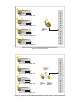
Figure 22, Basic System with I/O Machine Interface
(SLS-3 with SLR-2)
machine controller
Output to machine controller: 24 VDC from RECEIVE unit.
SLR-2
“RECEIVE”
unit
SLS-3 “SEND” unit
PALLET #1
Input #1
Input #2
Input #3
SLS-3 “SEND” unit
PALLET #2
Input #1
Input #2
Input #3
PALLET #1
Input #1
Input #2
Input #3
PALLET #2
Input #1
Input #2
Input #3
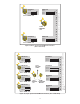
Output to machine controller: 24 VDC from RECEIVE unit and EXPANSION
MODULE.
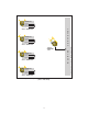
machine controller
PALLET #1
Input #1
Input #2
Input #3
PALLET #2
Input #1
Input #2
Input #3
PALLET #3
Input #1
Input #2
Input #3
PALLET #4
Input #1
Input #2
Input #3
PALLET #1
Input #1
Input #2
Input #3
PALLET #2
Input #1
Input #2
Input #3
PALLET #3
Input #1
Input #2
Input #3
PALLET #4
Input #1
Input #2
Input #3
SLR-2
“RECEIVE”
unit
SLEM-1
“EXPANSION
MODULE”
SLCS-1
“SPLITTER
CABLE”
Figure 23, Larger System with I/O Machine Interface (SLS-3 with SLR-2)
SLS-3 “SEND” unit
SLS-3 “SEND” unit
SLS-3 “SEND” unit
SLS-3 “SEND” unit