
Manual


5.2 Pendant and Motor Jog Buttons
(See Figures 5 and 6)
The pump motor can be controlled either by the pendant button
or by the motor jog button (located on the pump front panel).
Operation is the same for both
buttons:
Button pressed:
Motor starts. System pressure
builds and tool is actuated for as
long as button is held down.
Button released:
Motor stops. Check valve holds
pressure until pressure release
valve is opened.
Note: Pressure release valve (see Figure 4) must be fully closed
to allow pressure to build while motor is running.
5.3 Adjusting the Relief Valve Setting (See Figure 7)
1. Remove hose (if connected) from the quick disconnect
coupler at the oil outlet port.
2. Fully close the pressure release valve. See Figure 4.
3. Loosen the relief valve locknut to allow pressure adjustment.
See Figure 7.
4. Turn the relief valve knob several turns counter-clockwise, so
that the relief valve is set lower than the desired setting.
Notes:
• When adjusting relief valve setting, always start at a low
pressure and slowly increase the pressure to the desired setting.
• If desired, the motor jog button can be used in place of the
pendant button during the following steps.
5. Check that pump is connected to electrical power.
6. Press and hold the pendant button. See Figure 5. The pump
motor will start and pressure will begin building immediately.
7. While continuing to press and hold the pendant button,
slowly turn the relief valve knob clockwise (as required) until
the desired pressure reading is shown on the pump pressure
gauge.
WARNING: Pump maximum working pressure is
21,750 psi [1500 bar]. Do not set the relief valve
pressure above 21,750 psi [1500 bar].
8. Release the pendant button. The pump motor will stop.
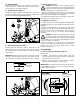
Locknut
Relief Valve
Knob
Figure 7, Relief Valve
Notes:
• Rotating the relief valve knob counter-clockwise will NOT
reduce or relieve existing system pressure.
• If pressure is adjusted too high, relieve pressure by opening the
pressure release valve (see Figure 4) until the pump pressure
gauge indicates zero (0) psi/bar. Then, fully close the pressure
release valve and repeat steps 6 through 8.
9. After verifying that setting is correct, tighten the relief valve
locknut (hand tight only - do not overtighten) to lock the
setting. See Figure 7.
10. Slowly open the pressure release valve to relieve pressure
in the oil outlet line. See Figure 4. Verify that pump pressure
gauge indicates zero (0) psi/bar.
5.4 Pressurizing the System
1. Adjust the relief valve setting. Refer to Section 5.3.
2. Connect hydraulic hose(s) and tool(s). Refer to Section 4.4.
3. Close the pressure release valve. See Figure 4.
4. Check that pump is connected to electrical power.
CAUTION: Before pressurizing the system, read and
understand all instructions and safety precautions
applicable to the hydraulic tool(s) being used. Follow
safe work practices in accordance with all applicable laws,
regulations and industry standards.
CAUTION: Continuously monitor the pump pressure
gauge while pump is running. Pressures can rise faster
than anticipated.
5. Press and hold the pendant button. See Figure 5. The pump
motor will start and pressure will begin building immediately.
6. When the desired reading is shown on the pump pressure
gauge, release the pendant button. The pump motor will
stop.
Note: Time required to pressurize the hydraulic circuit will vary,
depending on the number and type of tools connected, hydraulic
hose lengths and other factors.
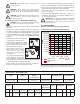
Pendant Button
Figure 5, Pendant
MOTOR
JOG
Figure 6, Motor Jog Button
4