Publication No: US-CYC-AM-007 - December 2008 - Subject to revisions without prior notice. E.&O.E.
Wherever the world needs stored energy, EnerSys® is there. Powered by more than 100 years of expertise, EnerSys® is the world’s largest industrial battery manufacturer, operating 21 facilities worldwide. Along with manufacturing and distributing a wide range of reserve power and motive power batteries, chargers, power equipment, and battery accessories, EnerSys provides unmatched aftermarket and customer support to its customers in over 100 countries worldwide.
Rugged construction and reliable performance in extreme temperatures make Cyclon batteries ideal for a range of applications: ® • Telecommunications • Defence installations • Aerospace • Global positioning systems • Uninterrupted Power Supply (UPS) Equipment • Emergency lighting • Medical equipment • Computer back-up • Electric vehicles • Solar power equipment • General electronics • Lawn and garden equipment 8 3
Powerful design: ® A CYCLON Single Cell Resealable safety valve A 50-PSI vent lets gases escape, then automatically reseals, so there’s no risk of excessive gas accumulation within the battery, or “dry out” failure from repeated recharges. Pure lead plates Made from 99.99% pure lead, CYCLON® battery plates are extremely thin, so they offer more surface area than conventional batteries - and far more power.
Table of Contents Chapter 1: 1.1 1.2 1.3 1.4 1.5 1.6 1.7 1.8 1.9 1.10 Introducing CYCLON® Batteries ..................................................................................................................... Introduction ........................................................................................................................................................ Sealed Design .................................................................................................................
Chapter 1: 1: Chapter Introducing the Genesis ® Introducing CYCLONBattery Batteries 1.1 Introduction The purpose of this guide is to describe the characteristics of the sealed-lead family of rechargeable CYCLON® cells and batteries from EnerSys® in its many different applications. The unique cylindrical design overcomes many limitations of competitive lead-acid systems without sacrificing cost effectiveness, reliability, ruggedness and long life which have always been assets of the lead-acid battery.
All CYCLON® cells and batteries are packaged, marked, labeled, and documented according to the appropriate transportation regulations when shipped from an EnerSys® facility. A shipper that fails to follow these same requirements may be subject to substantial civil and/or criminal penalties and may cause a safety hazard. The external spade terminals on CYCLON battery single cells are inserted through the polypropylene inner top and are effectively sealed by expansion into the lead busbars.
Higher currents than those shown in the table may be maintained for durations shorter than one minute. The ability of the cell or monobloc to maintain higher currents is dependent on the magnitude of the current, its duration, the frequency of its application and, most importantly, on the ability of the terminal connection to act as a heat sink and dissipate the heat generated. For high rate applications we strongly recommend testing under actual or simulated application conditions.
The movement of oxygen from the positive electrode to the negative electrode is facilitated by the use of highly porous separators that allow the oxygen to diffuse within the cell and cause the reaction defined by Equation 1. The acidic conditions prevailing inside the cell is very conducive to the reaction between lead oxide and the sulphuric acid to form lead sulphate in accordance with Equation 2 below: 3.
Figure 4-1: CYCLON® Battery Medium Rate Discharge Voltage Profile In "overdischarge" conditions, the sulphuric acid electrolyte can be depleted of the sulphate ion and essentially become water, which can create several problems. A lack of sulphate ions as charge conductors will cause the cell impedance to appear high and little charge current to flow. Longer charge time or alteration of charge voltage may be required before normal charging can resume. Cell Voltage (V) 2.3 2.2 C/5 C/10 2.1 2 1.9 1.8 1.
Figure 5-2: CYCLON® Battery Storage Time Vs. Temperature Chapter 5: CYCLON® Battery Storage 3000 Another area where the CYCLON® battery product has a significant advantage over conventional sealed-lead batteries is storage. This chapter devotes itself to offering the reader useful information on properly exploiting the long storage (shelf) life of CYCLON battery cells and monoblocs. Storage time, days 5.1 Introduction 1000 100 10 10 5.
If watt-hours rather than ampere-hours are measured, the required overcharge factor will be higher. It is important to note that although the battery can deliver at or near its full capacity prior to receiving the required overcharge, in order to obtain long cycle life, the battery must periodically receive the required overcharge. rate at which the charger is limited. In other words, if the charger is limited to the C10/10 rate, then 10 hours should be added, giving a total charge time of 26 hours.
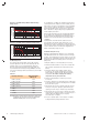
6.6 Float Charging Table 6-1 (1.5C10 inrush) Charge time at 2.45VPC Capacity Returned 17 min. 50% 27 min. 80% 31 min. 90% 60 min. 100% Table 6-2 (2.5C10 inrush) Charge time at 2.45VPC Capacity Returned 12 min. 50% 19 min. 80% 24 min. 90% 40 min. 100% These tables demonstrate the superior fast charge capabilities of the CYCLON® line of sealed-lead batteries. The numbers in Table 6-1 were generated using an initial current in the 1.
6.8 Constant Current (CC) Charging Constant current (CC) charging is another efficient method of charging CYCLON® battery single cells and monoblocs. CC charging of a cell or battery is accomplished by the application of a nonvarying current source. This charge method is especially effective when several cells are charged in series since it tends to eliminate any charge imbalance in a battery. CC charging charges all cells in the battery. Figure 6-2 is a family of curves depicting cell voltage vs.
6.9 Taper Current Charging A taper charger contains a transformer for voltage reduction and a half-wave or full-wave rectifier for converting the AC input into a DC output. The output characteristics are such that as the voltage of the battery rises during charge, the charging current decreases. This effect is achieved by using proper wire size and turns ratio.
The impact of undercharging is felt much earlier than that of overcharge. Hence, for cyclic applications, where the calendar life is relatively short, it is very important to ensure that the batteries are not undercharged. For cyclic applications, it is preferable to err on the side of overcharge than on the side of undercharge. The recommended charge voltage for cyclic applications is higher than that for float applications.
fire hazard. Particular caution should be used when the person working near the open terminals of cells or batteries is wearing metal rings or watchbands. Another consideration is the potential failure of the charger. If the charger malfunctions, causing higher-than-recommended charge rates, substantial volumes of hydrogen and oxygen will be vented from the cell. This mixture is explosive and should not be allowed to accumulate.
Table A-2: Watts per Single Cell Data to 1.67 VPC Figure A-2: Single Cell CP Graphs to 1.67 VPC D Tall D X E J BC 2 min. 5 min. 10 min. 15 min. 20 min. 30 min. 45 min. 1 hr. 2 hr. 3 hr. 4 hr. 5 hr. 8 hr. 10 hr. 20 hr. 42.2 25.5 16.3 12.3 10.0 7.3 5.3 4.2 2.3 1.6 1.2 1.0 0.70 0.50 0.30 52.9 39.0 27.3 21.2 17.3 12.8 9.3 7.3 3.9 2.7 2.1 1.7 1.1 0.90 0.46 62.4 44.2 30.5 23.6 19.4 14.4 10.4 8.2 4.5 3.1 2.4 1.9 1.2 1.0 0.50 85.3 64.4 45.8 36.0 29.8 22.3 16.3 12.9 7.1 4.9 3.8 3.1 2.0 1.6 0.80 95.2 79.
Table A-5: 2.5Ah Single Cell Data to 1.75 VPC Figure A-5: 2.5Ah Single Cell Discharge to 1.75 VPC Amps or watts per cell 100 Run Time at 25°C 10 1 0.1 0.01 0.1 10 1 50 Hours to 1.75 VPC at 25°C/77°F Amps Watts Amps or watts per cell 100 10 1 0.1 10 1 50 Hours to 1.85 VPC at 25°C/77°F Amps Watts Amps or watts per cell 100 10 1 0.1 10 1 Hours to 1.75 VPC at 25°C/77°F Amps www.enersys-emea.com Watts Watts per 2.5Ah Cell 21.2 13.1 8.4 6.3 5.1 3.7 2.7 2.1 1.15 0.80 0.60 0.50 0.
Table A-8: 4.5Ah Single Cell Data to 1.85 VPC Figure A-8: 4.5Ah Single Cell Discharge to 1.85 VPC Amperes per 4.5Ah Cell Watts per 4.5Ah Cell 2 min. 5 min. 10 min. 15 min. 20 min. 30 min. 45 min. 1 hr. 2 hr. 3 hr. 4 hr. 5 hr. 8 hr. 10 hr. 20 hr. 24.4 17.7 12.4 9.7 8.0 5.9 4.3 3.4 1.9 1.3 1.0 0.82 0.53 0.43 0.22 47.1 33.7 23.6 18.4 15.3 11.5 8.5 6.7 3.8 2.6 2.0 1.7 1.1 0.86 0.45 Table A-9: 5.0Ah Single Cell Data to 1.75 VPC 1 0.1 0.01 0.1 10 1 50 Hours to 1.
Figure A-11: 8.0Ah Single Cell Discharge to 1.75 VPC Amps or watts per cell 1000 100 10 1 0.1 0.01 0.1 10 1 50 Hours to 1.75 VPC at 25°C/77°F Amps Watts Figure A-12: 8.0Ah Single Cell Discharge to 1.85 VPC Amps or watts per cell 1000 100 10 1 0.1 0.01 0.1 10 1 50 Hours to 1.85 VPC at 25°C/77°F Amps Watts Figure A-13: 12.0Ah Single Cell Discharge to 1.75 VPC Amps or watts per cell 1000 100 10 1 0.1 0.01 0.1 10 1 Hours to 1.85 VPC at 25°C/77°F Amps www.enersys-emea.
Table A-14: 12.0Ah Single Cell Data to 1.85 VPC Figure A-14: 25.0Ah Single Cell Discharge to 1.75 VPC Amperes per 12.0Ah Cell Watts per 12.0Ah Cell 2 min. 5 min. 10 min. 15 min. 20 min. 30 min. 45 min. 1 hr. 2 hr. 3 hr. 4 hr. 5 hr. 8 hr. 10 hr. 20 hr. 33.5 32.2 25.9 21.4 18.3 14.2 10.7 8.6 4.8 3.4 2.6 2.1 1.4 1.1 0.60 64.1 60.3 48.5 40.3 34.5 27.0 20.4 16.5 9.5 6.7 5.2 4.3 2.8 2.3 1.2 Table A-15: 25.0Ah Single Cell Data to 1.75 VPC 10 1 0.1 0.01 0.1 10 1 50 Hours to 1.
NOTES www.enersys-emea.
Appendix B 1.60 VPC 1.50 VPC Run Time Amps Watts/cell Amps Watts/cell Amps Watts/cell Amps Watts/cell Amps Watts/cell 1.60 VPC 1.50 VPC Run Time Amps Watts/cell Amps Watts/cell Table B-6: CYCLON® BC Single Cell Performance 1.60 VPC 1.50 VPC Amps Amps Table B-4: CYCLON® E Single Cell and MB Performance Watts/cell Table B-5: CYCLON® J Single Cell Performance Run Time Run Time 1.60 VPC 1.50 VPC Amps 1.60 VPC 1.