MODEL BIO-45 MF OWNER’S MANUAL • • • • • • Warning: If your appliance is not properly installed a house fire may result. For your safety, follow the installation directions. Contact local building or fire officials about restrictions and installation inspection requirements in your area. PLEASE read this entire manual before installation and use of this pellet fuel-burning room heater. Failure to follow these instructions could result in property damage, bodily injury, or even death.
INTRODUCTION Thank you for purchasing the BIO-45 MF pellet stove. You are now prepared to burn wood in the most efficient, convenient way possible. To achieve the safest, most efficient and most enjoyable performance from your stove, you must do three things: 1) Install it properly; 2) Operate it correctly; and 3) Maintain it regularly. The purpose of this manual is to help you do all three. PLEASE read this entire manual before installation and use of this pellet fuel-burning room heater.
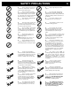
SAFETY PRECAUTIONS • Do not operate your stove if you smell smoke coming from it. Turn it off, monitor it, and call your dealer. • Never use gasoline, gasolinetype lantern fuel, kerosene, charcoal lighter fluid, or similar liquids to start or “freshen up” a fire in this stove. Keep all such liquids well away from the stove while in use. • Never block free airflow through the open vents of the stove. • Never try to repair or replace any part of the stove unless instructions are given in this manual.
TABLE OF CONTENTS INTRODUCTION --------------------------------------------------------------------------------------------SAFETY PRECAUTIONS ---------------------------------------------------------------------------------SPECIFICATIONS ------------------------------------------------------------------------------------------INSTALLATION --------------------------------------------------------------------------------------------Preparation ----------------------------------------------------------------
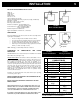
INSTALLATION 5 BIO-45 MF FREESTANDING PELLET STOVE Width: 27” Height: 30 1/2” Depth: 24 5” Weight: 230 lbs. Flue size: 3” or 4” Hopper Capacity: Up to 60 lbs. (This can vary widely depending on pellet size, length, and diameter) EPA status: certified Burn rate: 1.3 lbs to 5.5 lbs per hour BTU range: 8,200 to 45,000 Electrical consumption: 3.5 Amps lighting cycle 2.5 Amps. continuous duty Control board fuses: Main: 7.
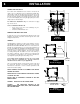
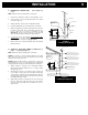
INSTALLATION COMBUSTION AIR SUPPLY For a mobile home installation the stove must be connected to an outside source of combustion air. A 3” inside diameter metallic pipe, either flexible or rigid, may be attached to the inlet at the stove’s rear (refer to figures 4, 5 & 6). A rodent guard (minimum ¼” wire mesh) must be used at the terminus (refer to figure 5). All connections must be secured and airtight by either using the appropriately sized hose clamp and/or UL-181-AP foil tape.
INSTALLATION Equivalent Vent Length (EVL) The longer the run of pipe in your installation, the greather the restriction there is in the system. Therefore, larger diameter pipe should be used. • Use 4” pipe if you have more than 15 feet of Equivalent Vent Length (EVL). • Horizontal runs shall not exceed 10 feet of EVL.
INSTALLATION Canada: Letter Min.
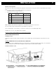
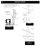
INSTALLATION A. HORIZONTALLY THROUGH WALL or 10) 9 (refer to Figure 7, 8, NOTE: Follow Vent chimney manufacturer’s instructions. 1. Position stove, adhering to clearances shown in Figures 1 & 2. 2. Locate position of hole in wall; directly behind stove exhaust vent (refer to figure 4). 3. Always maintain 3” clearance from combustible materials. 4. Install Vent wall thimble per Vent manufacturer’s instructions. 5.
INSTALLATION C. VERTICALLY INTO EXISTING CHIMNEY SYSTEM As an alternative, 3” or 4” Vent can be run inside existing chimney to termination(Figure 11). This is the preferred method. Follow guidelines for equivalent vent length.
INSTALLATION D. 11 VERTICAL ROOF VENT VERTICALLY INTO EXISTING MASONRY FIREPLACE 6" NOTE: Follow Vent chimney manufacturer’s instructions. 1. Have the masonry chimney inspected by a qualified chimney sweep or installer to determine its structural condition. 2. You will need a pipe length equal to the chimney height from the hearth. If outside combustion air is to be used, you will need a pipe length equal to the chimney height plus 18 inches. 3.
INSTALLATION OPTIONAL LOG SET INSTALLATION To install the optional log set, you first need to remove the four screws indicated on figure 14a. Keep the screws. Locate the two fixation brackets figure 14b that came with your owner’s manual. Fix the two brackets using the same screws you have removed.
INSTALLATION FILTERS INSTALLATION AND CLEANING The two filters for your convection blowers are supplied with the owner’s manual. Although the filters are not mandatory, they are useful to prevent dust from being dispersed into the room where the stove is located. If you install the filters, please make sure that they are cleaned on a regular basis as per our recommended maintenance schedule. This is particularly critical if you have animals in your house, such as a dog or a cat.
OPERATION PROPER FUEL THIS STOVE IS APPROVED FOR BURNING PELLETIZED WOOD FUEL ONLY! Factory-approved pellets are those ¼” or 5/16” in diameter and not over 1” long. Longer or thicker pellets sometimes bridge the auger flights, which prevents proper pellet feed. Burning wood in forms other than pellets is not permitted. It will violate the building codes for which the stove has been approved and will void all warranties.
OPERATION a. MODE SWITCH • When the mode switch is pressed, the stove will automatically ignite. If the manual mode is selected, the heat level must be selected manually to adjust the stove’s heat output to the desired level. If the thermostat mode is selected, the stove will automatically modulate between the lowest heat level and the heat level selected to keep the room temperature at the thermostat’s setting.
OPERATION IF THE STOVE RUNS OUT OF PELLETS The fire goes out and the auger motor and blowers will run until the stove cools down. This will take a few minutes. After the stove’s components stop running, a warning message will appear . To restart, press the “RESET” button, refill the hopper , and press the “FUEL FEED” button Press the “MODE” button to start the unit on Manual or Thermostatic mode. until pellets begin to fall into the burn pot.
THERMOSTAT INSTALLATION OPERATING THE STOVE USING A THERMOSTAT A thermostat may help you maintain a constant house temperature automatically. A millivolt thermostat or 24 Volt thermostat is required. A fixed wall mount or hand held model can be used. The control panel can be set up two ways to operate your stove in thermostatic mode. THERMOSTAT WIRES TERMINAL THERMOSTAT INSTALLATION • • • Unplug the stove from the power outlet.
THERMOSTAT INSTALLATION (continued) • N.B.: It is possible to change the setting of your unit such that if the thermostat does not call for heat after 45 minutes, the unit will remain at the lowest heat setting (#1) but will not shut down (this is the PILOT ON mode). The stove will remain at the lowest heat level until the thermostat calls for heat again.
OPERATION OPERATING SAFETY PRECAUTIONS PLEASE READ THIS! a. If you notice a smoldering fire (burnpot full but no visible flame) AND a heavy smoke buildup in firebox, immediately TURN OFF the stove, but DO NOT unplug it. Do not open the door, change the damper setting or tamper with any controls on the stove. Wait until smoke inside the firebox clears and blowers shut down. Do as instructed in “PRE-START-UP CHECK” and “LIGHTHING PROCEDURE”, then attempt to restart the fire.
MAINTENANCE FAILURE TO CLEAN AND MAINTAIN THIS UNIT AS INDICATED CAN RESULT IN POOR PERFORMANCE AND SAFETY HAZARDS. NEVER CLEAN WHEN HOT. NOTE: Inspect burn pot periodically to see that holes have not become plugged. If so, clean thoroughly. ASH REMOVAL Ashes should be placed in a metal container with a tight-fitting lid. The closed container or ashes should be placed on a noncombustible surface or on the ground, well away from all combustible materials pending final disposal.
MAINTENANCE ACCESS TO CLEANING OUTLET VACCUM USE If a vacuum is used to clean your stove, we suggest using a vacuum designed for ashes. 21 BAFFLE LEFT SIDE PANEL OF COMBUSTION CHAMBER Some regular vacuums and shop vacs leak ash into the room. Your vacuum or shop vac may have a special filter or bag available to eliminate this leakage. CLEANING a. b. c. Heat Exchange Tubes – Your BIO-45 MF stove is designed with a built-in heat exchanger tube cleaner.
MAINTENANCE CHIMNEY CLEANING a. b. c. Creosote Formation – When any wood is burned slowly, it produces tar and other organic vapors, which combine with expelled moisture to form creosote. The creosote vapors condense in the relatively cool chimney flue or a newly started fire or from a slowburning fire. As a result, creosote residue accumulates on the flue lining. When ignited, this creosote makes an extremely hot fire, which may damage the chimney or even destroy the house.
TROUBLESHOOTING GUIDE When your stove acts up, the first reaction is to call for help. This guide may save time and money by enabling you to solve simple problems yourself. Problems can be caused by to only five factors: 1) poor fuel; 2) poor operation or maintenance; 3) poor installation; 4) component failure; 5) factory defect. You can usually solve those problems related to 1 and 2. Your dealer can solve problems relating to 3, 4 and 5. Refer to figures 26 - 28 to help locate indicated parts.
TROUBLESHOOTING GUIDE STOVE SHUTS OFF AND DISPLAYS WARNING CODE Possible Causes: Possible Remedies: (Unplug stove first when possible) 1. The hopper is out of pellets. Refill the hopper. 2. The air damper is open too much for the low feed setting. If the stove is on the low setting, you may need to close the damper all the way. Slide the air supply control toward the minimum setting. 3. The burn pot holes are blocked. Remove the burn pot and clean it thoroughly. 4.
TROUBLESHOOTING GUIDE STOVE FEEDS PELLETS, BUT WILL NOT IGNITE AND APPEARS ON THE CONTROL BOARD Possible Causes: Possible Remedies: 1. Air damper open too far for ignition. Adjust the air supply to the minimum setting for startup. In some situations, it may be necessary to have the damper completely closed for ignition to take place. Once there is a flame, the damper can be adjusted to the desired feed setting. 2. Blockage in igniter tube or inlet for igniter tube.
TROUBLESHOOTING GUIDE 26 STOVE STOPS FEEDING PELLETS AND APPEARS ON THE CONTROL BOARD Possible Causes: Possible Remedies: 1. One of the two L-250 automatic high temperature switches has been tripped. The L-250 automatic high temperature switches are located on the top and bottom of the auger housing They send a signal to the control board if the auger housing overheats. Wait until the stove cools down AND THEN INSPECT YOUR UNIT.
TROUBLESHOOTING GUIDE • GLASS “SOOT’S” UP AT A VERY FAST RATE • FLAME IS LAZY, DARK, AND HAS BLACK TIPS • AFTER STOVE HAS BEEN ON FOR A WHILE, THE BURNPOT OVERFILLS Possible Causes: Possible Remedies: 1. Stove or vent pipe is dirty, which restricts airflow through the burn pot. Follow all cleaning procedure in the maintenance section of the owner’s manual. 2. Vent pipe installed improperly. Check to make sure the vent pipe has been installed according to the criteria in the owner’s manual. 3.
TROUBLESHOOTING GUIDE ALARM CODES CHART MESSAGE CORRESPONDING WARNING Pressure switch warning. Warning caused by one of the two automatic L-250 sensors: one is located under the pellet chute and the other one is inside the hopper heat shield . L-250 manual reset high temperature switch, located beside convection blower. Hopper is empty Lighting warning. Hopper lid stay open more than 3 minutes. Inverted polarity in power outlet. Power outage Igniter fuse is burnt out.
ELECTRICAL DIAGRAM THERMOSTAT TERMINALS N.O. HOPPER LID SWITCH N.O. CONTROL BOARD THERMISTOR L2(LINE COMMON) L1(LINE HOT) L1(LINE NO CONNECTED) FRAME GROUND L-250 RESET N.C. AIR FLOW PRESSURE SWITCH N.O. AUGER MOTOR L-250 N.C. COMBUSTION/EXHAUST BLOWER F-160 N.O.
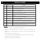
REPLACEMENT PARTS Contact an Authorized Enerzone Dealer to obtain any of these parts. Never use substitute materials. Use of non-approved parts can result in poor performance and safety hazards. ITEM Airflow Pressure Switch Air Switch Hose Auger Motor Burn Pot Control Board Combustion/Exhaust Blower Assembly Convection Blower Door Gasket Door Glass – Center Log support Exhaust Adapter 3” Hot Rod Igniter Thermistor F-160 Convection blower heat sensor L-250 Automatic High Temp.
APPENDIX A HORIZONTAL AND VERTICAL VENT CHART Possible Vertical vent length (feet) If you plot your venting system configuration on this chart, your wall or roof termination should be within the grid. Possible Horizontal vent length (feet) Let’s imagine an installation consisting of a horizontal vent coming out at the back of the stove on a total distance of 8 feet. This horizontal run is followed by a Tee and a 6-foot vertical rise. This type installation is not acceptable.
APPENDIX B Fabriquant de poêle international inc. Stove Builder International Inc. 1700, rue Léon-Harmel, Québec (Québec) G1N 4R9 Phone : (418) 527-3060 Fax : (418) 527-4311 E-mail : tech@sbi-international.com Web site : www.drolet.ca INSTALLATION DIAGRAM DRAW YOUR INSTALLATION 1 SQUARE = 1 F00T Installation int. ext.
ENERZONE LIMITED LIFETIME WARRANTY The warranty of the manufacturer extends only to the original consumer purchaser and is not transferable. This warranty covers brand new products only, which have not been altered, modified nor repaired since shipment from factory. Proof of purchase (dated bill of sale), model name and serial number must be supplied when making any warranty claim to your ENERZONE dealer. This warranty applies to normal residential use only.
29-10-2013
Maintenance 45 Serie CAUTION Before resetting your electronic card that displays an error code. • • Error Code H Service the stove COMPLETELY as described in this manual. Check the chimney pipe. • Error Code O Service the stove COMPLETELY as described in this manual. Check the chimney pipe Check the convection fan. • Error Code P Check that the Pressure switch pipe is not blocked. • THIS STOVE IS EQUIPPED WITH MULTIPLE DEVICES TO ENSURE YOUR SAFETY.
Maintenance 45 Serie MINIMUM RECOMMANDED MAINTENANCE SCHEDULE Components Daily Weekly Or after +/- 10 bags Burn Pot Empty Empty and Brush Glass Wipe Clean Heat Exchanger Tubes Activate the cleaning rod every time you load the stove Activate the cleaning rod and vacuum Baffle Empty and brush Convection Blower Filters Vacuum Ashe Drawer Empty Combustion Chamber Vacuum Monthly Or after +/- 25 bags Vacuum and Brush Left-hand Channel Vacuum Exhaust Blower Vacuum Pressure Switc
Maintenance 45 Serie REMOVE THE BAFFLE. 1. Lift the baffle and slide forward it a little to clear the supports. 2. Lower the baffle until the tab is behind the burn pot receptacle. 3. Rotate the baffle and align the right corner to the upper right corner of the door opening. 4. Continue rotating the baffle to remove it completely.
Maintenance 45 Serie CLEAN THE HEAT EXCHANGER TUBES. The cleaning rods must be activated as often as possible. #1 Pull and push the rod 4-5 times. #2These rods activate a rake that cleans the heat exchanger tubes. 1 Note: The stove will produce more heat if the heat exchanger tubes are clean. RECOMMENDED MAINTENANCE DAILY (It is not necessary to remove the baffle every day.
Maintenance 45 Serie CLEAN THE EXHAUST DUCTS 1 To access the exhaust ducts, remove the wall on the left side of the burning pot. 1. Remove 3 screws on the right and 2 screws left side of the panel. 2. Toggle the wall and remove it from the stove.
Maintenance 45 Serie CLEAN THE EXHAUST DUCTS NEXT. It is difficult to insert the vacuum hose into the openings. Using a ¾ inch hose installed on a vacuum adapter will facilitate access to these tight spaces. The cleaning of the exhaust ducts is made of 3 important openings. #1. A rectangle in the bottom and #2 A triangle at the top and also #3 opening above the heat exchanger tubes. 1 2 It is possible that an ash wall is formed and blocks the opening located above the tubes.
Maintenance 45 Serie CLEAN THE BURN POT. Using a scraper and a wire brush, thoroughly clean the surface of the burn pot. It is very important to leave no residue on the surface of the burn pot. Note: The sand and dirt contained in the wood pellets does not burn and solidifies to form a stone on the surface of the burn pot. This stone is commonly called (clinker) in the pellet stove industry.
Maintenance 45 Serie CLEAN THE BURN POT RECEPTACLE After removing the burn pot vacuum the ash within the burn pot receptacle. THE ASH DUMP CAP MUST BE IN PLACE. Vacuum the ash at the bottom of the pan and make sure the ash dump plug is in place and tight. RECOMMENDED MAINTENANCE DAILY EMPTY INSTALL 2 GASKETS IN THE RECEPTACLE BEHIND THE BURN POT. It is important to insert 2 Gaskets into the receptacle behind the burn pot. In the absence of gaskets the stove will not light easily.
Maintenance 45 Serie CLEANING THE EXHAUST FAN The Access to the exhaust fan is on the left side of the pedestal. Follow these steps To remove the left panel of the pedestal. 1 1. Unscrew the 2 retaining screws located behind the panel. 2. Pull the panel. 2 3. Push the panel forward.
Maintenance 45 Serie CLEANING THE EXHAUST FAN NEXT Remove the plate from the exhaust fan by unbolting the 4 bolts. Vacuum the ash and clean the fins of the fan using a small brush. Important: Make sure that the Gasket is in good condition. Change the gasket if needed before reinstalling the cleanout panel.
Maintenance 45 Serie CLEANING THE PRESSURE SWITCH TUBE. The pressure sensor is attached to the back grill of the stove to access the sensor open the left side panel of the stove. Remove the tube from the pressure sensor. Blow into the tube and ensure that the air passes freely. It is very Important to reinstall the tube on the pressure sensor taking care to connect the tube to the WHITE side of the sensor.
Maintenance 45 Serie THIS PELLET STOVE IS EQUIPED WITH MULTIPLE DEVICES TO ENSURE YOUR SAFETY. HOWEVER IF A WARNING ERROR CODE STOPS YOUR STOVE ON SEVERAL OCCASIONS, IT IS VERY LIKELY TO BE THAT THE STOVE DOES NOT EXAUSHT PROPELY. YOU HAVE THE RESPONSIBILITY TO MAKE SURE THAT THE MAINTENANCE OF THE STOVE IS DONE AS DESCRIBED IN THIS DOCUMENT. Before resetting the PC-board that displays an error code. Do FULL stove maintenance As described in this manual.
Maintenance 45 Serie TO RESET CODE O To reset the error code 0 in 3 steps. Error Code O 1. Unplug the stove 2. Reset the L250 manual. (See the photo on the left) 2 3. Press the button “RESET” On control panel. TO RESET ALL OTHER CODES Error code P Error code E Error code L Press the button “RESET” on the control panel. Error code d Error code n Error code I SMOKE SMELL OR SOOT BUILD: Because it is a solid fuel appliance, your pellet stove may emit odors of burnt wood.