
Specifications
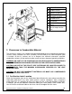

12 Euromax Pellet Stove Installation and Operation Manual
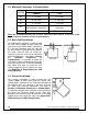
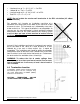
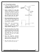
3.2 Minimum Clearances to Combustibles
LETTER
CLEARANCES TO COMBUSTIBLES
CANADA USA
A
3″ (76 mm) 3″ (76 mm)
B
6″ (152 mm) 6″ (152 mm)
C
3″ (76 mm) 3″ (76 mm)
D
Refer to vent
manufacturer’s clearances
Refer to vent manufacturer’s
clearances
I
72″ (1 829 mm) 72″ (1 829 mm)
Note
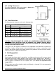
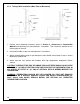
3.3 Back Wall Installation
: We recommend leaving 24″ on each side of the stove and 12″ at the back of the
stove in order to facilitate access for maintenance.
For a back wall installation, in order to allow
the LCD sliding support to move freely and
fully extend, you should allow a minimum of
6″ (152 mm)
clearance from the side wall
(B) and 3″(80 mm) clearance at the back of
the stove, from the fresh air intake (A).
However, if you wish to install the stove with
minimum clearances (see table in Section
3.2 Minimum Clearances to
Combustibles), it is possible to locate the
LCD touch screen elsewhere but within the
maximum length of the Telco wire provided.
You could also want to install the LCD
sliding support on the left side of the stove
(see Appendix B: Repositioning the LCD
Sliding Bracket).
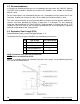
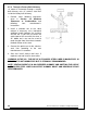
3.4 Corner Installation
For a corner installation, in order to allow the LCD
sliding support to move freely and fully extend, you
should allow a minimum of 6¼'' (160 mm) clearance to
the adjacent walls (C). However, if you wish to install
the stove with minimum clearances
(see table in
Section 3.2 Minimum Clearances to Combustibles),
it is possible to locate the LCD touch screen elsewhere
but within the maximum length of the Telco wire
provided. You could also want to install the LCD sliding
support on the left side of the stove (see Appendix B:
Repositioning the LCD Sliding Bracket).