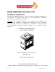
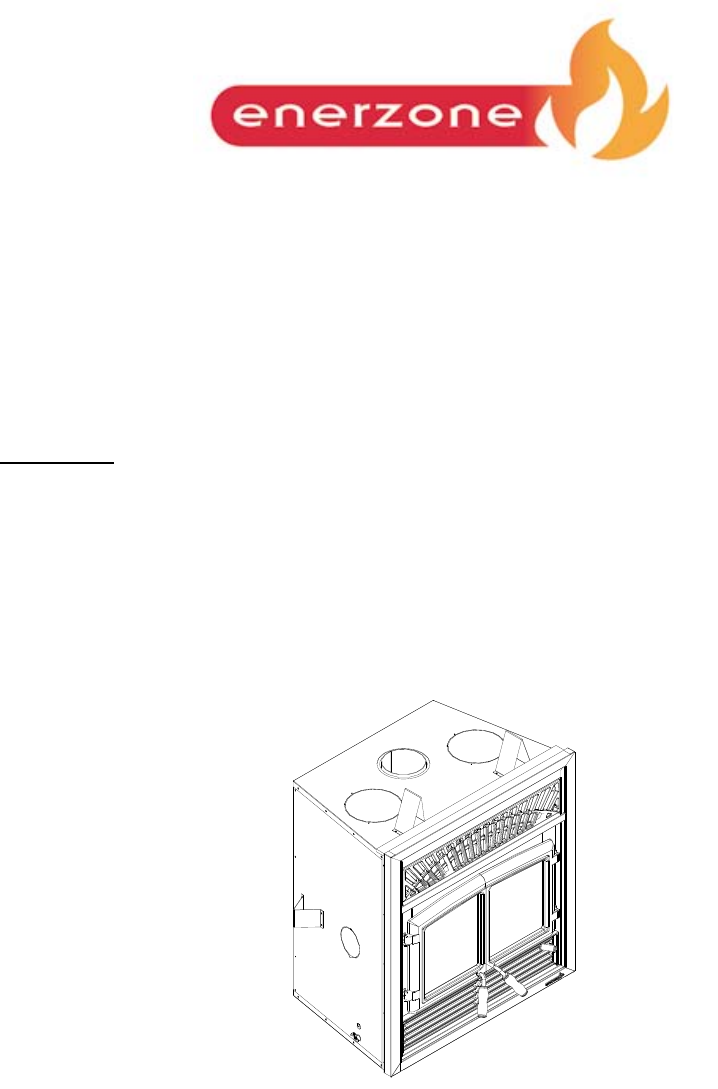
MODEL ENERZONE SOLUTION 2.5ZC Installation Instructions This installation manual will help you obtain a safe, efficient, dependable installation for your fireplace and chimney system. Please read and understand these installation instructions before beginning your installation. CAUTION: Do not attempt to modify or alter the construction of the fireplace or its components. Any modification or alteration of construction may void the warranty, listings and approvals of this system.
TABLE OF CONTENTS Page 1. SAFETY RULES FOR OPERATING YOUR FIREPLACE ....................................... 1 2. CERTIFICATION LABEL ......................................................................................... 3 3. THE FIREPLACE ..................................................................................................... 4 3.1 INTRODUCTION ..................................................................................................................4 3.1.1 Parts Required .....
4.1 CHIMNEY INSTALLATION NOTES ..............................................................................27 4.2 CHIMNEY INSTALLATION INSTRUCTIONS .............................................................28 4.3 OFFSET CHIMNEY INSTALLATION ............................................................................31 4.4 ANGLED WALL RADIATION SHIELD .........................................................................35 4.5 CHIMNEY SUPPORT INSTALLATION ....................................
1. SAFETY RULES FOR OPERATING YOUR FIREPLACE • Use only an Enerzone glass door, specifically designed for the model Enerzone Solution 2.5ZC. • When cleaning the fireplace, the ashes should be placed in a metal container with a tight fitting lid. The closed container of ashes should be placed on a non-combustible floor or on the ground outside the house, pending final disposal.
PLEASE NOTE THAT THE PICTURES SHOWN IN THIS MANUAL ARE GENERIC AND MAY NOT MATCH EXACTLY THE LOOK OF YOUR FIREPLACE. REGISTER YOU WARRANTY ONLINE To receive full warranty coverage, you will need to show evidence of the date you purchased your unit. Keep your sales invoice. We also recommend that you register your warranty online at www.enerzone-intl.com Registering your warranty online will help us track rapidly the information we need on your unit.
2.
3. THE FIREPLACE 3.1 INTRODUCTION The ENERZONE SOLUTION 2.5ZC fireplace is an energy efficient, heat circulating, close combustion fireplace. You will receive a lifetime of comfort and enjoyment from your fireplace provided it is installed, maintained and operated properly. • Please read these instructions and retain this manual for future reference. • Before beginning the fireplace installation, consult the local authorities to obtain your building permit and check your local building codes.
3.2 OPERATING THE ENERZONE SOLUTION 2.5ZC 3.2.1 Fuel The ENERZONE SOLUTION 2.5ZC is designed to work best when fuelled with seasoned cordwood. Use solid wood or processed solid fuel firelogs only. Hardwoods are preferred to softwoods since the energy content of wood is relative to its density. Hardwoods will result in a longer burning fire and less frequent refuelling. A moisture content of 15% to 20% (seasoned) is recommended.
3.2.3 First Fires The fresh paint on your fireplace needs to be cured to preserve its quality. Once the fuel load is properly ignited, only burn small fires in your fireplace for the first four hours of operation. Never open the air control more than necessary to achieve a medium burn rate. Make sure that there is enough air circulation while curing the stove. Open one or more windows. The odours can be smelled during the 3 or 4 first fires. 3.2.
the firebox. The benefit of this technique will be cleaner glass, less creosoting, greater efficiency and the most pleasing fire for your enjoyment. In order to achieve an optimum efficiency from your unit, we suggest that you operate it with the air control completely closed. Make sure that you have a good fire going and an adequate ember bed before you completely close the air control. Closing the air control too soon will lower combustion efficiency and may cause the fire to die out.
3.2.6 Primary Air There is no flue damper in the ENERZONE SOLUTION 2.5ZC. As in common with air tight stoves, the combustion air control sets the flow of air entering the firebox. This allows for a more precise control of the fire. The combustion air control is located below the door on the right side. The main source of air (primary air) entering the firebox can be diminished by moving the air combustion control from right to left.
Medium Combustion This is the recommended mode of operating the ENERZONE SOLUTION 2.5ZC and should be the one normally used since it will deposit the least amount of creosote on the glass and in the chimney. The combustion air control must be ¾ closed. The precise setting will depend on many factors, including chimney length and the moisture content of the wood. For instance, a long chimney will necessitate closing the combustion air control.
C. Wet wood Wet or tarred wood will smoulder and smoke instead of burning properly. D. Dirty or blocked chimney Check to make sure the chimney is clear and clean. E. Chimney not long enough The minimum system height is 15 feet (4.6m). The chimney must extend at least 3 feet (915 mm) above its point of contact with the roof and at least 2 feet (0.6 m) higher than any roof or wall within 10 feet (3 m) of it. When installed with offsets, the minimum system height is 15 feet (4.6 m) to 17 feet (5.
3.3 MAINTAINING YOUR ENERZONE SOLUTION 2.5ZC 3.3.1 Creosote – Formation and need for removal When wood is burned slowly without a flame, it produces tar and other organic vapours which combine with expelled moisture to form creosote. The creosote vapors condense in the relatively cool chimney flue of a slow-burning fire. As a result, creosote residue accumulates on the flue lining. When ignited this creosote makes an extremely hot fire.
FONT AIR TUBE Figure 2 3.3.4 Dealing with a Chimney Fire Regular chimney maintenance and inspection can prevent chimney fires. If you have a chimney fire, follow these steps: 1. Close the fireplace door and the combustion air controls; 2. Alert your family of the possible danger; 3. If you require assistance, alert your fire department; 4. If possible, use a dry chemical fire extinguisher, baking soda or sand to control the fire. Do not use water as it may cause a dangerous steam explosion; 5.
3.3.6 Disposal of Ashes Do not attempt to clean the fireplace when the unit is hot. Ashes should be placed in a metal container with a tight fitting lid. The closed container of ashes should be placed on a noncombustible floor or on the ground, well away from combustible materials pending final disposal. If the ashes are disposed of by burial in soil or otherwise locally dispersed they should be retained in the closed container until all cinders have thoroughly cooled. 3.3.
glass are maintained at hot. To clean the glass, there are a number of specially designed cleaners. Your authorized Enerzone dealer can recommend a suitable cleaner which is available in your area. Regular household glass cleaners will not clean creosote. Do not use abrasives such as steel pads, steel wool or oven cleaner as they will scratch the glass. Only wash when the stove is cold. 3.3.10 Gasket Replacement Remove the doors from the unit and lay them on a clean, unabrasive surface.
3.4 FIREPLACE INSTALLATION 3.4.1 Locating the ENERZONE SOLUTION 2.5ZC A. The best location to install your fireplace is determined by considering the location of windows, doors, and the traffic flow in the room where the fireplace is located, allowing space in front of the unit for the heart extension and the mantel, and taking into consideration the location of the hot air ducts (optional), outside air kit and chimney.
3.4.2 Heart Extension Requirements The ENERZONE SOLUTION 2.5ZC may be installed directly on a combustible floor; however, the combustible floor in front of the fireplace must be covered with a noncombustible material (tile, marble, stone, etc.). The hearth extension floor area shall extend at least 16" in front and at least 8" on each side of the fireplace opening. (see figure 4). The floor protector in front of the fireplace must have a R value of 1.53 or greater.
fireplace facing (within limitations of figure 11). Frame headers between the vertical studs only as follows: − Place 2" × 3" or 2" × 4" headers, only along the upper part of the front, side and back faces. Do not put wood or any combustible material within the area above the fireplace except on the front facing. − Place headers only as required to support the facing and mantel. D. WARNING: DO NOT PACK REQUIRED AIR SPACES WITH INSULATION OR OTHER MATERIALS.
STORM COLLAR ROOF SUPPORT FLASHING FLOOR / CEILING WALL ATTIC RADIATION SHIELD MUST HAVE THE SAME FIRESTOPPING RESISTANCE AS ADJACENT WALL. MUST HAVE THE SAME INSULATION AS ADJACENT CEILING. FOLLOW LOCAL RULES REGARDING FRAMING CONSTRUCTION. FIRESTOP NOTE: FLOOR AND WALL BELOW THE ATTIC MUST BE INSULATED USING THE SAME INSULATION. Spacers must be installed Spacers must be installed 7 MIN. FOYER GYPROC 2" X 4" 1/2" PLYWOOD Figure 9 Facing 1.
Combustible shelf Any combustible shelf must be installed at least 50" (127 cm) above the base of the fireplace if the depth of the shelf is 6" or less. If the depth of the shelf is more that 6" but less that 12", the shelf must be installed at least 52" (132 cm) from the base of the fireplace (see figure 10).
3.4.4 Blower connection The fan will come on as soon as the fireplace reaches its minimum start temperature. Have the wiring installed by a qualified electrician. Connect the wires from the power outlet to the terminal block, making sure that the white wire matches the white wire on the terminal. Connect the black wire with the black wire of the terminal block. The ground(green or skinned wire) must be attached to the fireplace metal frame.
3.5 HOT AIR DUCTING INSTALLATION Different hot air ducting systems can be installed with the ENERZONE SOLUTION 2.5ZC: − Gravity kit − Forced air kit 3.5.1 Gravity Kit The kit includes: − 2 x hot air outlets (grilles and frames); − 2 x 90o elbows with brackets; − 1 deflector. The gravity kit allows you to block the upper fireplace louver. To do so, follow the steps below: a) Remove the upper louver from the fireplace; b) Install the deflector as shown on figure 12; c) Put the upper louver back into place.
FIRESTOP FIRESTOP 10' MAX. 13" X 13" 10' MAX. Figure 14 RAIN CAP COLLAR FLASHING ROOF SUPPORT ATTIC RADIATION SHIELD FIRESTOP FACING Figure 15 The duct system must be installed respecting the following: 1. Remove the plates closing up the 8" dia. holes on top of the fireplace. Then, cut the insulation in order to obtain two 8" dia. openings. Insert the ducting into each opening and fix it in place using the 6 steel brackets supplied (3 for each duct). 2.
3. The maximum number of elbows in a run of duct is two. 4. Maintain at least 10" (254 mm) clearance from the outlet grille framing to a combustible ceiling, side wall or mantel. 5. When passing through a combustible wall or floor, a firestop must be installed at the wall or floor penetration. The hole size must be in accordance with the duct manufacturer’s instructions. 6. Do not connect the hot air ducts to a central heating system.
Since the forced air kit requires electricity, make sure that the connections to the fan have been made according to the local codes and comply with their requirements (see instruction provided with the kit).
3.6 FRESH AIR KIT (Optional) During operation, the fireplace requires fresh air for combustion and draws air out of the house. It may starve other fuel burning appliances such as gas or oil furnaces. As well, exhaust fans may compete for air, causing negative pressure in the house, resulting in smoke entering the house from the fireplace. This situation is aggravated in modern airtight houses. To overcome this problem, we strongly recommend that you install fresh air kit.
OUTSIDE AIR CONNECTION TO THE FIREPLACE FRESH AIR INTAKE ALUMINUM TAPE PLASTIC COVER OUTSIDE INTAKE FIRE PLACE CONNECTION FIREPLACE ALUMINUM TAPE 3" FLEXIBLE PIPE PLASTIC COVER FLEXIBLE PIPE SCREW OPENING FACING DOWN INSULATION ALUMINUM TAPE WALL ALUMINUM TAPE Figure 19 3.7 INSULATION Figure 20 DOOR OVERLAY INSTALLATION OVERLAY DOOR FRAME Figure 21 In order to install the door overlay, simply place the overlay over the door frame.
4. THE CHIMNEY 4.1 CHIMNEY INSTALLATION NOTES 1. If possible, install an interior chimney as it will provide better performance. In areas with continuous temperatures below −18° C (0° F), the use of an exterior chimney increases the likelihood of operating problems such as low draught, high rate of creosoting, and poor start-up characteristics. Exterior chimneys are also prone to down-drafting and flow reversal.
4.2 CHIMNEY INSTALLATION INSTRUCTIONS 1. Cut and frame the holes in the ceiling, floor and roof where the chimney will pass (see figure 23). Use a plumb bob to line up the center of the holes. Make sure that the size of the floor and ceiling holes are in accordance with the chimney manufacturer’s instructions. Figure 23 2. From below, install a firestop supplied by the chimney manufacturer in each ceiling/floor separation through which the chimney will pass.
EXAMPLE OF TYPICAL CHIMNEY INSTALLATION RAIN CAP COLLAR FLASHING ATTIC RADIATION SHIELD FIRESTOP OUTSIDE AIR KIT ANCHOR PLATE Figure 24 29
When you build a combustible chase enclosure for chimney sections above the roof, refer to the chimney manufacturer for clearances to combustible materials.
4.3 OFFSET CHIMNEY INSTALLATION The minimum system height when using elbows is: Fireplace model ENERZONE SOLUTION 2.5ZC Chimney model All models Vertical installation 15 ft. (4.6 m) Two (2) elbows 15 ft. (4.6 m) Four (4) elbows 17 ft. (5.2 m) Table 1 After reaching the location requiring the elbow, proceed as follows: 1. Install the first elbow; turn it in the required direction. Secure it to the chimney according to the chimney manufacturer’s instructions.
SUPPORT STRAPS STRAPS CHIMNEY ANCHOR PLATE Figure 26 RAIN CAP COLLAR ROOF FLASHING 15' FRAMING 2" X 3" OFFSET SUPPORT 18" INSULATED WALL RADIATION SHIELD Figure 27 32
TABLE 2 - LISTED CHIMNEYS FOR YOUR ENERZONE SOLUTION 2.
TABLE 3 – LIST OF MANDATORY COMPONENTS CHIMNEY MANUFACTURER Selkirk Security Chimney MANDATORY COMPONENTS • • Ventilated roof flashing. Must have rafter protectors at the roof level if the chimney is enclosed at the attic level (see section 5). • Rafter protector at the roof level if chimney is enclosed at the attic level (see section 5). Requires insulated attic radiation shield unless chimney is enclosed at the attic level. Ventilated roof flashing.
4.4 ANGLED WALL RADIATION SHIELD When passing through a combustible wall with the chimney at a 30° or 45° angle (30° or 45° in Canada and 30° only in the USA), an angled firestop or wall radiation shield provided by the chimney manufacturer must be installed. Only one is required. Follow the chimney manufacturer’s installation instructions. In cold climate locations, it is recommended that you use the insulated wall radiation shield since it will maintain the home’s thermal barrier.
4.5 CHIMNEY SUPPORT INSTALLATION Universal Roof Support This support has three possible uses: 1. It must be used on a roof to support the chimney. 2. It may be used on a floor, ceiling or roof above an offset to support the chimney above the offset. 3. It may be used on a floor, ceiling or roof as a supplementary support. For roof support installation, refer to the instructions provided with the support by the chimney manufacturer.
18" 457.2mm 18" 457.2mm 18" 457.21mm 16" 406.4mm 16" 406.
4.7 INSTALLATION INSTRUCTIONS FOR MASONRY APPLICATION WARNING: Before starting the installation, the masonry chimney must be inspected by a qualified sweep. The following requirements must be respected: 1. The chimney must be absolutely clear of any soot residue or creosote. Check for cracks, loose or missing bricks that could inhibit correct installation of the liner. 2. The clearance to combustible must be a minimum of 1" between the outside of the masonry and any wood framing or loose insulation. 3.
5. OPTIONS Gravity kit: Part No.: Includes: one deflector, two 90o elbows, and two outlet grilles and frames, . #AC01309 Central forced air kit: Includes: one blower, one 5" flex adapter, 3 pipe clamps, And one control box with heat sensor and PC Board. #AC01310 Outside air kit Includes: one 3" flex adapter, 2 pipe clamps, and one outside wall register. #AC03500 Rigid spark screen Includes: one rigid spark screen.
6. APPENDIX SPECIFICATIONS Weight: 385 lbs Height: 38" Width: 36.75" Depth: 26" Maximum recommended heating area : 500 to 2,100 square feet (with forced air kit) Heating capacity* – BTU/hr., EPA test wood : 30,500 Heating capacity* – BTU/hr.
REPLACEMENT PARTS Description Part No. Description Front air tube (1) PL53030 Bricks (side and rear) 29020 Air tube (2) – second from front PL53031 Left floor brick 22122 Air tube (3) – third from front PL53032 Right floor brick 22123 Back air tube (4) PL53033 Flue insulation collar 21152 44073 Vermiculite baffle 21134 Blowers Top insulation (2 ½” thick) 21150 Door glass Part No.
7. ENERZONE LIMITED LIFETIME WARRANTY The warranty of the manufacturer extends only to the original consumer purchaser and is not transferable. This warranty covers brand new products only, which have not been altered, modified nor repaired since shipment from factory. Products covered under this warranty must have been manufactured after the revision date indicated below.