INSTALLATION AND OPERATION MANUAL Solution 2.5-ZC US ENVIRONMENTAL PROTECTION AGENCY PHASE II CERTIFIED WOOD FIREPLACE Listed to standards ULC-S610 and UL 127 by Intertek Testing Services www.enerzone-intl.com Stove Builder International Inc. 250, rue de Copenhague, St-Augustin-de-Desmaures (Quebec) Canada G3A 2H3 Tel: (418) 878-3040 Fax: (418) 878-3001 READ AND KEEP THIS MANUAL FOR REFERENCE This manual is available for free download on the manufacturer’s web site. It is a copyrighted document.
THANK YOU FOR CHOOSING THIS ENERZONE WOOD FIREPLACE As one of North America’s largest and most respected wood stove and fireplace manufacturers, Stove Builder International takes pride in the quality and performance of all its products. We want to help you get maximum satisfaction as you use this product.
Table of content PART A - OPERATION AND MAINTENANCE ............................... 6 1 Safety Information ..................................................................... 6 1.1 Summary of Operation and Maintenance Cautions and Warnings ......................... 6 2 General Information................................................................... 9 2.1 Solution 2.5-ZC Specifications ............................................................................... 9 2.
5 Maintaining Your Wood Heating System .............................. 26 5.1 Fireplace Maintenance ......................................................................................... 26 5.1.1 Plated Finish Maintenance ................................................................................ 26 5.1.2 Glass Door Cleaning ......................................................................................... 26 5.1.3 Door Adjustment ...............................................................
8.8 Chimney Support Installation ............................................................................... 66 8.8.1 Universal Roof Support ..................................................................................... 66 8.8.2 Universal Offset Support ................................................................................... 67 8.9 Installation Instructions for Masonry Application .................................................. 67 8.10 Supply of Combustion Air ......................
PART A - OPERATION AND MAINTENANCE Please see Part B for installation instructions. 1 Safety Information 1.1 Summary of Operation and Maintenance Cautions and Warnings • HOT WHILE IN OPERATION, KEEP CHILDREN, CLOTHING AND FURNITURE AWAY. CONTACT MAY CAUSE SKIN BURNS. GLOVES MAY BE NEEDED FOR FIREPLACE OPERATION. • USING A FIREPLACE WITH CRACKED OR BROKEN COMPONENTS, SUCH AS GLASS OR FIREBRICKS OR BAFFLES MAY PRODUCE AN UNSAFE CONDITION AND MAY DAMAGE THE FIREPLACE.
• DO NOT BURN: o o o o o o o o o GARBAGE OF ANY KIND, COAL OR CHARCOAL, TREATED, PAINTED OR COATED WOOD, PLYWOOD OR PARTICLE BOARD, FINE PAPER, COLORED PAPER OR CARDBOARD, SALT WATER DRIFTWOOD, MANUFACTURED LOGS CONTAINING WAX OR CHEMICAL ADDITIVES, RAILROAD TIES OR LIQUIDS SUCH AS KEROSCENE OR DIESEL FUEL TO START A FIRE. • THIS APPLIANCE SHOULD BE MAINTAINED AND OPERATED AT ALL TIMES IN ACCORDANCE WITH THESE INSTRUCTIONS. • DO NOT ELEVATE THE FIRE BY MEANS OF GRATES, AND IRONS OR OTHER MEANS.
WARNING: THIS FIREPLACE HAS NOT BEEN TESTED WITH AN UNVENTED OR VENTED GAS LOG SET. TO REDUCE RISK OF FIRE OR INJURY, DO NOT INSTALL AN UNVENTED GAS LOG SET INTO THIS FIREPLACE. CAUTION: DO NOT INSTALL IN A MOBILE HOME (CANADA) OR MANUFACTURED HOME* (USA). * The US department of Housing and Urban Development describes “manufactured homes” better known as “mobile home” as followed; Buildings built on fixed wheels and those transported on temporary wheels/axles and set on a permanent foundation.
2 General Information 2.1 Solution 2.5-ZC Specifications Fuel Type Cordwood Test Standards (safety) ULC-S610 and UL 127 Test Standard (emissions) EPA Method 28 (40 CFR Part 60) Heating capacity range* 500 to 2100 sq. ft. (46.5 to 195 m2) Maximum heat output** (EPA test fuel) 30,450 BTU/h (8.9 kW/h) Maximum heat output** (natural hardwood fuel) 75,000 BTU/h (22 kW/h) Optimum efficiency 77 % Particulate Emissions 4.
Solution 2.
Solution 2.
2.2 Zone Heating and How to Make it Work for You Your new Solution 2.5-ZC wood fireplace is a space heater, which means it is intended to heat the area it is installed in, as well as spaces that connect to that area, although to a lower temperature. This is called zone heating and it is an increasingly popular way to heat homes or spaces within homes.
2.4 The SBI Commitment to You and the Environment The SBI team is committed to protecting the environment, so we do everything we can to use only materials in our products that will have no lasting negative impact on the environment. 2.4.1 What is Your New Fireplace Made Of? The body of your fireplace, which is most of its weight, is carbon steel.
3 Fuel 3.1 Materials That Should Not be Burned • GARBAGE OF ANY KIND, • COAL OR CHARCOAL, • TREATED, PAINTED OR COATED WOOD, • PLYWOOD OR PARTICLE BOARD, • FINE PAPER, COLORED PAPER OR CARDBOARD, • SALT WATER DRIFTWOOD • MANUFACTURED LOGS CONTAINING WAX OR CHEMICAL ADDITIVES • RAILROAD TIES • LIQUIDS SUCH AS KEROSENE OR DIESEL FUEL TO START A FIRE WARNING: DO NOT POKE OR STIR THE LOGS WHILE THEY ARE BURNING.
Note that hardwood trees like oak, maple, ash and beech are slower growing and longer lived than softer woods like poplar and birch. That makes hardwood trees more valuable. The advice that only hardwoods are good to burn is outdated. Old, leaky cast iron stoves wouldn’t hold a fire overnight unless they were fed large pieces of hardwood. That is no longer true. You can successfully heat your home by using the less desirable tree species and give the forest a break at the same time. 3.2.
Wood should be split to a range of sizes, from about 3” to 6” (75 mm to 150 mm) in cross section. Having a range of sizes makes starting and rekindling fires much easier. Often, the firewood purchased from commercial suppliers is not split finely enough for convenient stoking. It is sometimes advisable to resplit the wood before stacking to dry. 3.2.5 How to Dry Firewood Firewood that is not dry enough to burn is the cause of most complaints about wood fireplaces.
3.2.
4 Operating Your Fireplace 4.1 The use of a fire screen This fireplace has been tested for use with an open door in conjunction with a fire screen (AC01308, sold separately). Make sure the fire screen is properly secured on the fireplace to avoid any risk of sparks damaging your flooring. When the fire screen is in use, do not leave the fireplace unattended so that you can respond promptly in the event of smoke spillage into the room.
4.3.1 Conventional Fire Starting The conventional way to build a wood fire is to bunch up 5 to 10 sheets of plain newspaper and place them in the firebox. Next, place 10 or so pieces of fine kindling on the newspaper. This kindling should be very thin; less than 1” (25 mm). Next, place some larger kindling pieces on the fine kindling. Open the air control fully and light the newspaper. If you have a tall, straight venting system you should be able to close the door immediately and the fire will ignite.
of knots is that they don’t roll off the fire as they burn. Light the newspaper and watch as the fire burns from top to bottom. 4.3.3 Two Parallel Logs Place two spit logs in the firebox. Place a few sheets of twisted newspaper between the logs. Now place some fine kindling across the two logs and some larger kindling across those, log cabin style. Light the newspaper. 4.3.4 Using Fire Starters Many people like to use commercial fire starters instead of newspaper.
IF YOU MUST OPEN THE DOOR WHILE THE FUEL IS FLAMING, OPEN THE AIR CONTROL FULLY FOR A FEW MINUTES, THEN UNLATCH AND OPEN THE DOOR SLOWLY. 4.4.2 Ash Removal Ash should be removed from the firebox every two or three days of full time heating. Do not let the ash build up in the firebox because it will interfere with proper fire management.
4.4.4 Firing Each New Load Hot Place the new load of wood on and behind the charcoal, and not too close to the glass. Close the door and open the air control fully. Leave the air control fully open until the firebox is full of flames, the wood has charred to black and its edges are glowing red.
4.4.6 Building Different Fires for Different Needs Using the air control is not the only way to match the fireplace’s heat output to the heat demand. Your house will need far less heat in October than in January to be kept at a comfortable temperature. If you fill the firebox full in fall weather, you will either overheat the space or turn the fireplace down so much that the fire will be smoky and inefficient. Here are some suggestions for building fires to match different heat demand. 4.4.6.
fully char the log surfaces before you can turn the air down. Make sure the fire is flaming brightly before leaving the fire to burn. 4.4.6.3 High Output Fires for Cold Weather When the heat demand is high during cold weather, you’ll need a fire that burns steadily and brightly. This is the time to use larger pieces of hardwood fuel if you have it. Put the biggest pieces at the back of the firebox and place the rest of the pieces compactly.
4.4.6.5 How to place the logs In fireboxes that are roughly square, wood can be loaded so that looking through the glass door you see the ends of the logs (north-south) or the sides of the logs (east-west). In all cases, wood should always be placed behind the andirons. East-west loads that are built compactly break down slowly when heated, but the amount of wood you can load is limited because if you put in too many pieces, one may fall against the glass.
5 Maintaining Your Wood Heating System 5.1 Fireplace Maintenance Your new fireplace will give many years of reliable service if you use and maintain it correctly. Some of the internal components of the firebox, such as firebricks, baffles and air tubes, will wear over time under intense heat. You should always replace defective parts with original parts (see Appendix 7: Exploded Diagram and Parts List).
Do not abuse the glass door by striking or slamming shut. Do not use the fireplace if the glass is broken. 5.1.3 Door Adjustment In order for your fireplace to burn at its best efficiency, the door must provide a perfect seal with the firebox. Therefore, the gasket should be inspected periodically to check for a good seal. The gasket seal may be improved with a simple latch mechanism adjustment. To adjust: 1. Remove the split pin by pulling and turning it using pliers. 2.
5.1.4 Door Alignment To align, open the fireplace’s doors and loosen the pressures screws located on the lower and upper hinges of each door using a 3/32” Allen key to free the adjustable hinge rods. 28 Solution 2.
Using a flat screwdriver, turn the adjustable hinge rods in the direction shown to adjust the doors. Tighten all door hinge pressure screws when they are at the desired positions. Solution 2.
5.1.5 Replacing the Door Gasket It is important to maintain the gasket in good condition. After a year or more of use, the door gasket will compress and become hard, which may allow air to leak past it. You can test the condition of the door gasket by closing and latching the door on a strip of paper. Test all around the door. If the paper slips out easily anywhere, it is time to replace the gasket. Use the correct replacement gasket that you can purchase from your retailer.
The gasket must be centred on the edge of the glass. To do this easily, peel back a section of the paper covering the adhesive and place the gasket on a table with the adhesive side up. Stick the end of the gasket to the middle of one edge, then press the edge of the glass down onto the gasket, taking care that it is perfectly centred on the gasket. Peel off more of the backing and rotate the glass and press the next section onto the gasket. Do not stretch the gasket as you place it.
with fine sand paper, wipe it down to remove dust, and apply two thin coats of paint. For best results, use the same paint that was originally used on the fireplace, which is available in spray cans. See your dealer for details. 5.2 Chimney and Chimney Liner Maintenance 5.2.1 Why Chimney Cleaning is Necessary Wood smoke can condense inside the chimney liner and chimney, forming a combustible deposit called creosote.
5.2.3 Cleaning the Chimney Chimney cleaning can be a difficult and dangerous job. If you don’t have experience cleaning chimneys, you might want to hire a professional chimney sweep to clean and inspect the system for the first time. After having seen the cleaning process, you can decide if it is a job you would like to take on. The most common equipment used are fibreglass rods with threaded fittings and stiff plastic brushes.
5.2.4 Fire Baffle Removal Prior to Cleaning the Chimney Before starting to clean your chimney, we recommend that you remove the fire baffle to avoid creosote dust collection on top of the baffle. Follow the steps below to remove the fire baffle: 1. Remove the front air tube by pulling out the cutter pin on the side of the tube. They are located at the top, underneath the baffle. 2. Lift the baffle assembly and slide it out of the fireplace. You now have access to the chimney.
PART B – INSTALLATION Install the fireplace only as described in these instructions and using only components from the chimney manufacturers listed in table 2. Parts Required SOLUTION 2.5-ZC Fireplace Insulated chimney made by the manufacturers listed in table 2, with the corresponding specifications : Chimney lengths Elbows (where necessary) Associated components as per these installation instructions.
• IF REQUIRED, A SUPPLY OF COMBUSTION AIR SHALL BE PROVIDED TO THE ROOM. • DO NOT CONNECT TO OR USE IN CONJUNCTION WITH ANY AIR DISTRIBUTION DUCTWORK UNLESS SPECIFICALLY APPROVED FOR SUCH INSTALLATION. • DO NOT CONNECT THIS UNIT TO A CHIMNEY FLUE SERVING ANOTHER APPLIANCE. • THIS FIREPLACE HAS NOT BEEN TESTED TO BE INSTALLED IN A MOBILE HOME. • THIS FIREPLACE HAS NOT BEEN TESTED TO BE INSTALLED INSIDE A MASONRY CHIMNEY. 6.
NOTE: The Fireplace is not approved for use with a so-called “positive flue connection” to the clay tile of a masonry chimney. 6.3 Fireplace Installation 6.3.1 Locating the SOLUTION 2.5-ZC A.
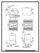
CLEARANCES A B MINIMUM MEASUREMENTS 80" (2032 mm) 4" (102 mm) minimum E 38 Solution 2.
Solution 2.
In the case where (F) would be equal to 4", it is suggested that the sheet metal between the base of the fireplace and floor be in one piece. 40 Solution 2.
6.3.1.2 On the floor or on a raised base of less than 4" installation (R value for the hearth extension required) In the case where the fireplace is installed directly on the floor or on a raised base of less than 4", an R value for the hearth extension is required. In these case also, the joint between the hearth extension and the fireplace (E) must be protected by a noncombustible material. For example, a sheet metal (not included).
A noncombustible floor protection with R value insulation equal to or greater than 1.00 must be installed in front of the unit. For more details see Section 6.3.2: Minimum Heart Extension Requirements. The use of an R value is convenient when more than one material is going to be used in the hearth extension to cover the combustible surface. This is because R values are additive, whereas K values are not.
Thermal Characteristics of Common Floor Protection Materials* MATERIAL Micore® 160 Micore® 300 Durock® Hardibacker® Hardibacker® 500 Wonderboard® Cement mortar Common brick Face brick Marble Ceramic tile Concrete Mineral wool insulation Limestone Ceramic board (Fibremax) Horizontal still air** (1/8") CONDUCTIVITY (k) PER INCH 0.39 0.49 1.92 1.95 2.3 3.23 5.00 5.00 9.00 14.3 – 20.00 12.5 1.050 0.320 6.5 0.450 0.135 RESISTANCE (R) PER INCH THICKNESS 2.54 2.06 0.52 0.51 0.44 0.31 0.2 0.2 0.11 0.07 – 0.05 0.
CLEARANCES A B C 16" (406 mm) 41.5" (1054 mm) 8" (203 mm) 44 Solution 2.
6.3.3 Framing, Facing, Mantel, and Combustible Shelf 6.3.3.1 Framing The construction of the framing, facing, and mantel must be in accordance with the standards and the following illustrations: A. Frame the sides and back of the fireplace using 2" × 3" (5 cm x 8 cm) or heavier lumber. However, the front studs as well as headers on top of the fireplace must be of a depth no more than the depth of the top standoffs.
Wall finish behind the fireplace’s faceplate installation Wall finish adjacent to the fireplace’s faceplate installation MEASUREMENTS CLEARANCES A B* C* D* 5 5/16" (135 mm) 8 7/16" (215 mm) 5" (127 mm) 80" (2032 mm) E* F* G 35 7/8" (911 mm) 24 1/2" (622 mm) 7/8" (22 mm) MAX *When drywall panels or any other finishing material inside the chase around the fireplace is to be used, add its thickness to the measurement. 46 Solution 2.
See Appendixes for fresh air kit (L) and forced air kit (K) installation. Fresh air intake kit or forced air kit installation J* H* MINIMUM MEASUREMENTS FOR FRESH AIR INTAKE** 12" (305 mm) 12" (305 mm) MINIMUM MEASUREMENTS FOR FORCED AIR KIT** 18" (457 mm) 18" (457 mm) *When drywall panels or any other finishing material inside the chase around the fireplace is to be used, add its thickness to the measurement.
MEASUREMENTS** MEASUREMENTS F* G I* 36 1/2" (927 mm) 7/8" (22 mm) MAX 18” (457 mm) M* N* 51 5/8" (1311 mm) 73" (1854 mm) *When drywall panels or any other finishing material inside the chase around the fireplace is to be used, add its thickness to the measurement. **Values M and N are minimum measurements. They may need to be increased to alloy installation of a Fresh air intake kit or forced air kit, or depending on the finish material used. 48 Solution 2.
CLEARANCES A B C 3" (76 mm) maximum 5 5/8" (143 mm) minimum 17" (432 mm) minimum Solution 2.
6.3.3.2 Facing Materials directly in contact with the faceplate of the fireplace may be combustible. Non-combustible material such as brick, stone or ceramic tile may be in contact with the fireplace decorative frame. Note that if you ever needed to remove the decorative frame, it might be wise not to seal between the faceplate and finishing material. LEGEND Combustible material allowed in this area 6.3.3.
A CLEARANCES SHELF POSITIONING 80" (2032 mm) B C 50" (1270 mm) 6" (152 mm) 52" (1321 mm) 8" (203 mm) 54" (1372 mm) 10" (254 mm) 56" (1422 mm) 12" (305 mm) Solution 2.
7 Clearances to Combustible Material The clearances shown in this section have been determined by test according to procedures set out in safety standards ULC S610 (Canada) and UL127 (U.S.A.). When the fireplace is installed so that its surfaces are at or beyond the minimum clearances specified, combustible surfaces will not overheat under normal and even abnormal operating conditions. No part of the fireplace may be located closer to combustibles than the minimum clearance figures given.
8 The Venting System 8.1 General The venting system, acts as the engine that drives your wood heating system. Even the best fireplace will not function safely and efficiently as intended if it is not connected to a suitable chimney. The heat in the flue gases that pass from the fireplace into the chimney is not waste heat. This heat is what the chimney uses to make the draft that draws in combustion air, keeps smoke inside the fireplace and safely vents exhaust to outside.
There are two reasons why the chimney in the house at right will cold backdraft when it is cold outside and there is no fire burning in the fireplace. First, the chimney runs up the outside of the house, so the air in it is colder and denser than the warm air in the house. And second, the chimney is shorter than the heated space of the house, meaning the negative pressure low in the house will pull outside air down the chimney, through the fireplace and into the room.
8. If the chimney extends higher than 5 ft. (1.5 m) above its point of contact with the roof, it must be secured using a roof brace. 9. A rain cap must be installed on top of the chimney. Failure to install a rain cap may cause corrosion problems. 10. Cut and frame square holes in all floors, ceilings, and roof that the chimney will go through to provide a 2" (50 mm) minimum clearance between the chimney and any combustible materials.
12. For installations where more than one chimney is located in the same non-chase or within the same area, we suggest that their terminations be separated by at least 16" (410 mm) horizontally, and 18" (460 mm) vertically. This separation is to prevent smoke migrating from one chimney to another. 18" 457.2mm 18" 457.2mm 18" 457.21mm 16" 406.4mm 16" 406.4mm 56 Solution 2.
8.6 Chimney Installation Instructions Always refer to the chimney manufacturer’s Installation manual to ensure a safe installation. Some non-illustrated parts may be required. 8.6.1 Examples of Typical Chimney Installation A To insure a good draft, it is recommended to have a length of 18 inches from the top of the unit to the first offset. However, starting using a 30° or 45° elbow is also approved. B Mandatory measure of 15 ft. from the bottom of the fireplace to the top of the outside chimney.
Direct installation 58 Solution 2.
Interior offset installation Connection to a masonry chimney 1. Cut and frame the holes in the ceiling, floor and roof where the chimney will pass. Use a plumb bob to line up the center of the holes. Make sure that the size of the floor and ceiling holes are in accordance with the chimney manufacturer’s instructions. 2. From below, install a firestop (B) supplied by the chimney manufacturer in each ceiling/floor separation through which the chimney will pass.
3. Follow the chimney’s manufacturers’ instructions and place the first chimney length on the fireplace. For all chimneys, you must use an anchor plate (A) supplied by the chimney manufacturer before installing the first chimney length. Continue installing chimney lengths making sure to lock each length in place. 4. Every time the chimney passes through a ceiling or a wall, install the appropriate firestop. When you reach the desired height, install the roof support (not illustrated).
** THE STRUCTURAL INTEGRITY OF THE FLOOR, WALL, AND CEILING/ROOF MUST BE MAINTAINED NOTE: THE FLOOR AND WALLS BELOW THE ATTIC MUST BE INSULATED USING THE SAME INSULATION.. Solution 2.
8.6.2 Offset Chimney Installation Table 1 - The minimum system height when using elbows is: Fireplace model SOLUTION 2.5-ZC Chimney model All models Vertical installation 15 ft. (4.6 m) Two (2) elbows 15 ft. (4.6 m) Four (4) elbows 17 ft. (5.2 m) After reaching the location requiring the elbow, proceed as follows: 1. Install the first elbow; turn it in the required direction. Secure it to the chimney according to the chimney manufacturer’s instructions.
TABLE 2 - LISTED CHIMNEYS FOR YOUR SOLUTION 2.
Refer to the following table to determine the parts you will need depending on the type of fireplace used: (R: Required, NR: Not Required). Reference in figure bellow. Parts required.
TABLE 3 – LIST OF MANDATORY COMPONENTS CHIMNEY MANUFACTURER Selkirk MANDATORY COMPONENTS Ventilated roof flashing. Must have rafter protectors at the roof level if the chimney is enclosed at the attic level. Rafter protector at the roof level if chimney is enclosed at the attic level. Requires insulated attic radiation shield unless chimney is enclosed at the attic level. 1" Solid Pack: ASHT+, Requires the use of a 6AW7 2" Solid Pack : S-2100 (Solid pack 1") adapter for a ASHT+ of 7".
8.7 Angled Wall Radiation Shield When passing through a combustible wall with the chimney at a 30 or 45 angle (30 or 45 in Canada and 30 only in the USA), an angled firestop or wall radiation shield provided by the chimney manufacturer must be installed. Only one is required. Follow the chimney manufacturer’s installation instructions. In cold climate locations, it is recommended that you use the insulated wall radiation shield since it will maintain the home’s thermal barrier.
For roof support installation, refer to the instructions provided with the support by the chimney manufacturer. Many manufacturers will provide the maximum height of chimney that can be supported by the support. Make sure you respect those parameters. 8.8.2 Universal Offset Support This support is used to support the chimney above an offset. When the chimney offset is used to pass through a wall, this support may be used on the wall to support the chimney.
Follow these steps: 1. Position the fireplace in its location. Temporarily install the elbow or chimney section (A) on the top of the fireplace and, using a level, mark with an oval the location where the flue liner will enter the masonry chimney. 2. In the middle of the oval, drill a hole in the masonry chimney at 45 or 30. 3. Increase the size of the hole until a 45 or 30 insulated liner adapter (B) can be easily slipped through. 4.
8.10.1 Air Supply in Conventional Houses The safest and most reliable supply of combustion air for your wood fireplace is from the room in which it is installed. Room air is already preheated so it will not chill the fire, and its availability is not affected by wind pressures on the house. Contrary to commonly expressed concerns, almost all tightly-sealed new houses have enough natural leakage to provide the small amount of air needed by the fireplace.
Appendix 1: Hot Air Ducting Installation Different hot air ducting systems can be installed with the SOLUTION 2.5-ZC: Gravity kit Forced air kit Gravity Kit (AC01309) The kit includes: 2 x hot air outlets (grilles and frames); 2 x 90o elbows with brackets; 1 block-off plate. The gravity kit allows you to block the upper fireplace louver.
The hot air grilles can be installed in the same room as the fireplace, or one or both of the grilles can be installed in adjacent or upper rooms. Installing the ducts at different elevations will tend to exhaust more heat out of the higher grilles. Solution 2.
The duct system must be installed respecting the following: 1. Remove the plates closing up the 8" dia. holes on top of the fireplace. Then, cut the insulation in order to obtain two 8" dia. openings. Insert the ducting into each opening and fix it in place using the 6 steel brackets supplied (3 for each duct). 2. Maintain at least a 2" (50 mm) clearance between the ducts and the firestop; the required hole size for the hot air grilles (outlet) is 8¼" × 8¼" (210 mm × 210 mm). 3.
Central Forced Air Kit (not tested to EPA Standards) (AC01340) The knock-outs provided on the back and on the sides of the SOLUTION 2.5-ZC allow the connection of insulated flexible pipe which enables you to heat adjacent rooms up to 50 feet from the fireplace. This HVAC type pipe must comply with ULC S110 and/or UL 181, Class 0 or Class 1 Standards and must withstand temperatures up to 250 °F. For the complete installation procedure, see the installation manual provided with the kit.
Appendix 2: Blower Maintenance or Replacement 1. Remove the bottom louver (A). 2. With a short square head screwdriver, remove the 4 screws (C) holding in place the heat shield (B). 74 Solution 2.
3. Remove and keep the heat shield (B) and the 4 screws (C). 4. Cut the Tie wrap (D) Solution 2.
5. Unplug the blower’s electric wires (F) and (G). 6. Lift the blower (E) located under the firebox towards the back. 7. Turn 90° to pull out. Repeat the steps in reverse order to reinstall the fan. 76 Solution 2.
Blower connection Have the wiring installed by a qualified electrician. Connect the wires from the power outlet to the terminal block, making sure that the white wire matches the white wire on the terminal. Connect the black wire with the black wire of the terminal block. The ground (green or skinned wire) must be attached to the fireplace metal frame. Solution 2.
Appendix 3: Installing the Door Overlay In order to complete the assembly of your Solution 2.5-ZC wood fireplace, you need to install the door overlay. See figure below for installation instructions: Position the overlays (A) and (B) on the door frames and secure them from the inside of the doors using the 8 included screws (B). To facilitate the installation, do not tighten the screws until they are all installed. Note: It is not necessary to remove the glass or any other component to install the overlay.
Appendix 4: Installing the Adapter for Fresh Air Kit (AC03500) During operation, the fireplace requires fresh air for combustion and draws air out of the house. It may starve other fuel burning appliances such as gas or oil furnaces. As well, exhaust fans may compete for air, causing negative pressure in the house, resulting in smoke entering the house from the fireplace. This situation is aggravated in modern airtight houses.
Note: Only remove the knock-out that will be connected to the fresh air inlet. To install a fresh air intake to the fireplace, the purchase of accessory AC03500 adapter is required (sold separately). The fresh air intake kit may be installed on three different places on the fireplace. 1- On the right side of the appliance (most common). 2- On the right side, at the back of the appliance. 3- On the right side under the appliance.
Remove the fireplace’s lower decorative louver. Install the blocking plate (F) included in the kit, on the front opening of the air control housing. Using a screwdriver, secure with two screws. Then, install the flexible pipe* (D) (not supplied) to the fresh air intake adapter (B) using one of the adjustable pipe clamps (C). Secure the other end of the pipe to the outside wall termination (E) using the second adjustable pipe clamp (C).
To complete the installation, make a hole of1/4" to 1/2" (6 mm à 13 mm) bigger than the insulate pipe diameter in the outside wall of the house at the chosen location. From outside, place the outside air inlet cap in the hole (open side down) and fasten the register to the wall, with screws as shown bellow. Place the insulated pipe over the register tube and over the fireplace outside air connector. At each end, carefully pull back the insulation and plastic cover, exposing the flexible pipe.
Appendix 5: Installing the Fire Screen (AC01308) Open the doors. Hold the fire screen by the two handles and bring it close to the door opening. Lean the upper part of the fire screen against the top door opening making sure to insert the top fire screen bracket behind the primary air deflector as in (DETAIL A). Lift the fire screen upwards and push the bottom part towards the stove then let the fire screen rest on the bottom of the door opening.
Appendix 6: Installation of Secondary Air Tubes and Baffle REMOVABLE PARTS A Cotter pins (x4) B Air tubes (x4) C C-cast baffle (x1) D Baffle insulation (x1) E Baffle insulation weight (x1) 1. Starting with the rear tube, lean and insert the right end of the secondary air tube into the rear right channel hole. Then, lift and push the tube towards the right inside the hole in the right channel. 84 Solution 2.
2. Align the notch in the left end of the tube with the tab of the left air channel hole. 3. Insert a cotter pin in the last hole on the right side of the tube. Then bend the tabs on the pin to keep in place. 4. Repeat steps 1, 2 and 3 for the two tubes in the back then install the baffle. Then, install the two front tubes. 5. To remove the tubes use the above steps in reverse order. Note that secondary air tubes can be replaced without removing the baffle board. Solution 2.
Important Notes: The air tubes are identified for placement as follows: Model Type of tube SOLUTION 2.5-ZC fireplace Front ► 95 holes of 0.141" Middle front ► 67 holes of 0.125’’ Middle rear ► 67 holes of 0.109’’ Rear ► 67 holes of 0.101’’ 86 Solution 2.
Appendix 7: Exploded Diagram and Parts List Solution 2.
IMPORTANT: THIS IS DATED INFORMATION. When requesting service or replacement parts for your stove, please provide the model number and the serial number. We reserve the right to change parts due to technology upgrade or availability. Contact an authorized dealer to obtain any of these parts. Never use substitute materials. Use of non-approved parts can result in poor performance and safety hazards.
# Item Description Qty 32 30579 ADJUSTABLE HINGE PIN 3/8'' - 5/16'' DIA X 1 63/64'' LONG 4 33 30117 SOCKET SET SCREW #10-32 X 1/4" 4 34 PL53141 RH SIDE OF FACEPLATE 1 35 99999 BUILD TO ORDER 1 36 PL53150 LH SIDE OF FACEPLATE 1 37 60201 CONNECTOR 1 SCREW 3/8" FOR BX WIRE 1 38 44046 THERMODISC F110-20F 1 39 99999 BUILD TO ORDER 1 40 44084 RHEOSTAT WITH NUT 1 41 44087 RHEOSTAT NUT 1 42 44085 RHEOSTAT KNOB 1 43 44091 ROCKER SWITCH 2 POSITION MSR-8 1 44 44122
Refractory Replacement The intense heat of the fire will normally cause hairline cracks in the refractory. These cracks can be minimized by proper curing as described in “First Fires”. They will not normally diminish the effectiveness of the refractory. If large cracks develop, then the refractory should be replaced. To replace the refractory bricks, follow these steps: 1. Remove all bricks (A) surrounding the combustion chamber. 2.
3. Remove the floor bricks (E) & (F). To install the new bricks, follow the above steps in reverse. Solution 2.
ENERZONE LIMITED LIFETIME WARRANTY The warranty of the manufacturer extends only to the original consumer purchaser and is not transferable. This warranty covers brand new products only, which have not been altered, modified nor repaired since shipment from factory. Products covered under this warranty must have been manufactured after the revision date indicated below.