User Manual: GSM0000PB001MAN Enfora GSM/GPRS Spider SA User Manual Revision 1.07 Enfora L.P. 661 E. 18th Street Plano Texas 75074 www.enfora.
GSM/GPRS Spider SA User Manual Document Title: Enfora GSM/GPRS Spider SA User Manual Version: 1.07 Date: 02/14/05 Status: Released Document Control ID: GSM0000PB001MAN General All efforts have been made to ensure the accuracy of material provided in this document at the time of release. However, the items described in this document are subject to continuous development and improvement.
GSM/GPRS Spider SA User Manual Limited Warranty ENFORA L.P. 12-MONTH LIMITED WARRANTY Enfora warrants to the original purchaser of the product that, for a period of one (1) year from the date of product purchase, the product hardware, when used in conjunction with any associated software (including any firmware and applications) supplied by Enfora, will be free from defects in material or workmanship under normal operation.
GSM/GPRS Spider SA User Manual (ii) caused by any accident, misuse, abuse, improper installation, handling or testing, or unauthorized repair or modification of the product, (iii) caused by use of any software other than any software supplied by Enfora, or by use of the product other than in accordance with its documentation or (iv) the result of electrostatic discharge, electrical surge, fire, flood or similar causes.
GSM/GPRS Spider SA User Manual Revision History Revision Number 1.00 1.
GSM/GPRS Spider SA User Manual Table Of Contents 1 2 3 4 5 Introduction ....................................................................................................1 1.1 About the GSM/GPRS Spider SA...........................................................1 1.2 About this Manual...................................................................................1 1.3 System Requirements ............................................................................2 1.
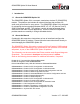
GSM/GPRS Spider SA User Manual 1 1.1 Introduction About the GSM/GPRS Spider SA The GSM/GPRS Spider SA is a compact, stand-alone wireless IP (GSM/GPRS) modem. The platform also includes an external interface that provides I/O, audio, and ground lines for easy access. The GSM/GPRS Spider SA is designed for computing devices operating Windows 98 SE, XP, NT 4.0 (Service Pack 6), 2000 Professional and ME. The platform can also be used as a stand-alone serial device with other vertical applications.
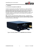
GSM/GPRS Spider SA User Manual 1.3 System Requirements • • • Windows 98 SE / XP / NT 4.0 (Service Pack 6)/2000 Professional / ME operating systems or other serial-enabled platform One standard RS-232 serial port for GSM/GPRS Spider SA configuration One standard plug for speaker and microphone* *not required for stand alone operation 1.4 Spider SA Front and Back View Figure 1: Front view of GSM/GPRS Spider SA modem. Figure 2: Rear view of GSM/GPRS Spider SA modem. GSM0000PB001MAN 2 Version 1.
GSM/GPRS Spider SA User Manual 2 Regulatory Compliance FCC • The modem was tested and certified to meet FCC Parts 15 in a stand-alone configuration, which demonstrated that the GSM/GPRS Spider SA complies with Part 15 emission limits. FCC Part 24 is covered by the Enfora Enabler-G "modular approval" process for a transmitter.
GSM/GPRS Spider SA User Manual 3 Installation 3.1 Subscriber Identity Module (SIM) Card The SIM, an integral part of any GSM terminal device, is a “smart card” that is programmed with subscriber information. The user information consists of an International Mobile Subscriber Identity (IMSI) number, which is registered with the GSM service provider, and an encryption Ki (pronounced “key”). This information consists of a microprocessor and memory installed on a plastic card.
GSM/GPRS Spider SA User Manual 3.2 Connecting the Power Supply The GSM/GPRS Spider SA modem can utilize input power ranging from 5 Vdc to 30 Vdc. If your unit did not include a power supply or if you wish to configure a separate power interface, the following connector parts can be used to mate with the existing modem power connector: Connector Pins - Molex 39-00-0207 MINIFIT TERM CRP FEM CHN BS TIN 18-24 Plastic Housing - Molex 39-01-2020 4.20mm (.165") Pitch Mini-Fit, Jr.
GSM/GPRS Spider SA User Manual The following tables provide the power characteristics of the GSM/GPRS Spider SA modem. Enfora Enabler-G (@ 12 Volts) Average Current (mAmps) Peak Current (Amps) GSM 900 GSM 1 TX 1 RX 1 RX Idle Sleep 150 mA 76 mA 21 mA 20 mA .88 A @ 32.5 dBm DCS 1800 & PCS 1900 GSM 1 TX 1 RX 1 RX Idle Sleep 112 mA 72 mA 21 mA 20 mA .58 A @ 29.
GSM/GPRS Spider SA User Manual 3.3 Connecting the Serial Cable To connect the Spider SA with a local computing device, connect one end (male end) of the 9-wire RS232 Serial Cable to the Spider SA port labeled “Serial” and connect the other end to a computer. Figure 5: Connecting the Serial Cable to Spider SA The following figure provides the Spider SA serial pinout information. Figure 6: Serial Pinout GSM0000PB001MAN 7 Version 1.
GSM/GPRS Spider SA User Manual 3.4 Connecting the GSM/GPRS Antenna The antenna is supplied by the user. The antenna must have a nominal impedance of 50 Ohms. The VSWR must be less than 2.0:1. System antenna gain should be 0-2 dB for optimum performance. See section 2 Regulatory Compliance FCC. There are two varieties of GSM/GPRS Spider SA modems. Model number GSM1202 operates at the 900/1800 MHz frequency band while model number GSM1203 operates in 1900 MHz frequency band.
GSM/GPRS Spider SA User Manual 3.5 Attaching a Microphone/Speaker To place a voice call, insert a microphone/speaker to the port labeled “MIC AUDIO” as shown below in Figure 8. The plug is a standard 2.5mm audio connector. Many existing mobile phone headsets can be used. Figure 8: Attaching a Headset to the GSM/GPRS Spider SA Module GSM0000PB001MAN 9 Version 1.
GSM/GPRS Spider SA User Manual 3.6 Using the GSM/GPRS Spider SA Modem I/O Interface The GSM/GPRS Spider SA Modem provides an external I/O connector that can be used to interface with other devices. The mating I/O connector and operating tool part numbers are provided below: Wago I/O Connector – 733-108 FEMALE CONNECTOR WITH CAGE-CLAMP - 8 POLE Connector Tool – 233-332 OPERATING TOOL FOR FRONT-ENTRY WIRING OF SERIES 233 The Wago connector is attached to the SA as shown in Figure 9.
GSM/GPRS Spider SA User Manual The I/O pin configuration is provided in Figure 11. Figure 11: GPIO Pin Configuration Five general-purpose signals (GPIO1, GPIO3, GPIO5, GPIO6, and GPIO7) are provided. Each of these signals may be selected as inputs or outputs. The GPIO characteristics are provided in Table 3. One audio input and one audio output line is provided along with a ground line.
GSM/GPRS Spider SA User Manual 3.8 Mounting the GSM/GPRS Spider SA The GSM/GPRS Spider SA ships with a mounting bracket for remote installation The bracket should be used as a template to mark screw holes for installation. See Figure 12: GSM/GPRS Spider SA Mounting Bracket (attached). The mounting holes are designed for a number 10 screw.
GSM/GPRS Spider SA User Manual Figure 13: GSM/GPRS Spider SA Mounting Bracket (separated) Figure 14: GSM/GPRS Spider SA Bracket Installation GSM0000PB001MAN 13 Version 1.
GSM/GPRS Spider SA User Manual Figure 15: GSM/GPRS Spider SA Mounting Bracket (ready to mount) Figure 16: Mounting Bracket Dimensions GSM0000PB001MAN 14 Version 1.
GSM/GPRS Spider SA User Manual 4 Frequently Asked Questions (FAQ) Q. How do I configure a PPP connection for the Windows 98? A. Refer to “GSM0000AN001 - Enabler-G PPP Configuration for Windows 98” application note for details. Q. How do I configure a PPP connection for Windows 2000? A. Refer to the “GSM0000AN002 - Enabler-G PPP Configuration for Windows 2000” application note for details. Q. How do I send and receive data and voice calls to/from a remote host? A.
GSM/GPRS Spider SA User Manual Q. How can I use the Dynamic IP reporting feature on the Spider SA? A. Refer to the “GSM0000AN009 - Dynamic IP Assignment Support” application note for details. Q. How do I configure a PPP connection for PocketPC 2002? A. Refer to the “GSM0000AN0010 - Enabler-G PPP Configuration for PocketPC 2002” application note for details. Q. How can I use the UDP Packet Assembler/Disassembler feature on the Spider SA? A.
GSM/GPRS Spider SA User Manual 5 Tech Support For problems stemming from your network access, contact your GSM/GPRS carrier service. For technical support and customer service dealing with the modem itself, contact the company where you purchased the product. If you purchased the product directly from Enfora, visit the SUPPORT page on the Enfora website: http://www.enfora.com. GSM0000PB001MAN 17 Version 1.