MLG0208PB001 Enfora Enabler II-G Assisted GPS Integration Guide Version: 1.01 Enfora, Inc. 661 E. 18th Street Plano Texas 75074 www.enfora.
Enfora Enabler II-G Assisted GPS Modem Integration Guide Document Title: Enfora Enabler II-G Assisted GPS Integration Guide Version: 1.01 Date: 10/3/06 Status: Released Document Control ID: MLG0208PB001 General All efforts have been made to ensure the accuracy of material provided in this document at the time of release. However, the items described in this document are subject to continuous development and improvement.
Enfora Enabler II-G Assisted GPS Modem Integration Guide Table of Contents 1. Safety Precautions............................................................................................................................... 1 1.1. 2. 3. Important Safety Information ...................................................................................................... 1 Regulatory Compliance FCC ..............................................................................................................
Enfora Enabler II-G Assisted GPS Modem Integration Guide 6. Physical Interfaces ............................................................................................................................ 20 6.1. Physical Layout ................................................................................Error! Bookmark not defined. 6.2. Module Pin Orientation Reference............................................................................................ 22 6.3. Connectors.....................
Enfora Enabler II-G Assisted GPS Modem Integration Guide 9.4. 10. Selecting the GSM Modes of Operation ................................................................................... 46 Software Interface .......................................................................................................................... 46 10.1. Software Interface ................................................................................................................... 46 10.2.
Enfora Enabler II-G Assisted GPS Modem Integration Guide 14.8. Instructions to the Original Equipment Manufacturer (OEM)............................................. 68 14.8.1. OEM Responsibilities for All Products Containing the Enabler II-G A-GPS module............. 70 14.8.2. Specific OEM Responsibilities for Portable Products and Applications ................................ 71 14.8.3. Specific OEM Responsibilities for Mobile Products and Applications................................... 71 14.8.4.
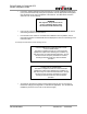
Enfora Enabler II-G Assisted GPS Modem Integration Guide 1. Safety Precautions 1.1. Important Safety Information The following information applies to the devices described in this manual. Always observe all standard and accepted safety precautions and guidelines when handling any electrical device. • Save this manual: it contains important safety information and operating instructions. • Do not expose the Enfora Enabler II-G A-GPS product to open flames.
Enfora Enabler II-G Assisted GPS Modem Integration Guide • If used in a "mobile" application where the antenna is normally separated at least 20 cm (7.9 in) from the human body during device operation, then an appropriate warning label must be placed on the host unit adjacent to the antenna. The label should contain a statement such as the following: WARNING RF exposure. Keep at least 20 cm (7.9 in) separation distance from the antenna and the human body.
Enfora Enabler II-G Assisted GPS Modem Integration Guide • The transmitter and antenna must not be co-located or operating in conjunction with any other antenna or transmitter. Violation of this would allow a user to plug another transmitter in to the product and potentially create an RF exposure condition. WARNING The transmitter and antenna must not be collocated or operating in conjunction with any other antenna or transmitter. Failure to observe this warning could produce an RF exposure condition.
Enfora Enabler II-G Assisted GPS Modem Integration Guide 3. Manual Overview This document describes the hardware interface of the Enabler II-G Assisted GPS (A-GPS) modem. The purpose of this document is to define the electrical, mechanical and software interfaces while providing detailed technical information in order to streamline the process of hardware and system integration. 3.1. Revision History Date 9/18/2006 10/3/2006 Rev 1.00 1.
Enfora Enabler II-G Assisted GPS Modem Integration Guide 3.2. Reference Documents 3.2.1.
Enfora Enabler II-G Assisted GPS Modem Integration Guide Technical Notes • GSM0000TN001 - Enabler-G Firmware Upgrade • GSM0000TN002 - Enabler-G PPP Negotiation Sequence • GSM0000TN006 - UDP Wakeup Message Header Decoding • GSM0000TN007 - Enabler-G 3-Wire Serial Interface Requirements • GSM0000TN008 - Enabler Power Supply Requirements • GSM0000TN009 - Server Application Design Considerations for Dynamic IP • GSM0000TN012 – Enabler II-G Engineering Mode Command Reference • GSM0000TN013 – Enabler II-G and IIE
Enfora Enabler II-G Assisted GPS Modem Integration Guide 3.2.8. Mechanical Specifications • • • • • • • 3.2.9. ASTM D999 ASTM D775 IEC 68-2-27 Bellcore Gr-63-CORE ETS 300 019-1-1 Class 1.2 ETS 300 019-1-2 Class 2.1 ETS 300 019-1-3 Class 3.1 RF and EMI Specifications • • • • • ETSI Standards EN 61000-4-6 EN 61000-4-3 3GPP TS 51.010-1, Section 12.2 EN 55022 Class B MLG0208PB001 7 Version1.
Enfora Enabler II-G Assisted GPS Modem Integration Guide 4. Introduction 4.1. Product Overview Enfora Enabler II-G A-GPS modem is a compact, wireless OEM module that utilizes the Global System for Mobile Communications (GSM) and GPRS (General Packet Radio Services) international communications standard to provide two-way wireless capabilities via GSM services.
Enfora Enabler II-G Assisted GPS Modem Integration Guide GSM/GPRS Functionality GPS Functionality SIM • Mobile-originated and mobile-terminated SMS messages: up to 140 bytes or up to 160 GSM 7-bit ASCII characters. • Reception of Cell Broadcast Message • SMS Receipt acknowledgement • Circuit Switched Data (Transparent & Non-transparent up to 9.
Enfora Enabler II-G Assisted GPS Modem Integration Guide Figure 1 – UDP API Architecture 4.5. GSM/GPRS System Overview The Enfora Enabler II-G A-GPS module is shown in Figure 1 is designed for easy integration with other components and packaging by leveraging the existing GSM networks. Compare the Enfora Enabler II-G A-GPS to systems that require construction, operation, maintenance, and expense of a private network. MLG0208PB001 10 Version1.
Enfora Enabler II-G Assisted GPS Modem Integration Guide Figure 2 - PAD Architecture MLG0208PB001 11 Version1.
Enfora Enabler II-G Assisted GPS Modem Integration Guide 4.6. Assisted GPS System Overview Normally, the GPS receiver provides a position with latitude and longitude information after it decodes ephemeris data of the satellites in view. The process of searching for satellites, and decoding its ephemeris can take anywhere from tens of seconds to hundreds of seconds.
Enfora Enabler II-G Assisted GPS Modem Integration Guide 4.7. Summary of Features for the Enabler II-G A-GPS Module The following summarizes the main features of the Enfora Enabler II-G A-GPS Module. Mechanical Dimensions................................... 46.0 mm x 30.2 mm x 3.1 mm Weight ..........................................
Enfora Enabler II-G Assisted GPS Modem Integration Guide Application Interface: Host Protocol................................ Status API and AT Commands Internal Protocols ......................... UDP stack, TCP/IP stack, PPP, PAD, and CMUX Physical Interface......................... (2) Serial 16550 – Default rate 115,200 baud Audio Interface ............................. 1 Headset w/Mic & Bias, 1 Mic w/Bias, 1 Earphone SIM Interface: Remote SIM Option 1.
Enfora Enabler II-G Assisted GPS Modem Integration Guide GSM Transmit Power 1800/1900 MHz............................ GSM Power Class 1 (30 dBm ± 2 dB @ antenna connection) 850/900 MHz ................................ GSM Power Class 4 (33 dBm ± 2 dB @ antenna connection) GSM/GPRS Receiver Sensitivity (Typical) 1800/1900 MHz............................ <-106 dBm, GPRS Coding Scheme 1 (CS1) 850/900 MHz ................................ <-106 dBm, GPRS Coding Scheme 1 (CS1) GPS Operation Power Tracking........
Enfora Enabler II-G Assisted GPS Modem Integration Guide 5. Technical Specifications 5.1. Enabler II-G A-GPS Module Block Diagram Power Audio Analog Baseband / Power Mgnt GPRS Ant. Interface RF Interface GPRS RF SIM GPIO Quad-Band PA Digital Baseband CPU GPS BB RF Interface GPS Ant. Interface GPS RF Serial Interface SRAM / FLASH TCXCO Figure 3 Enabler II-G A-GPS Module Block Diagram MLG0208PB001 16 Version1.
Enfora Enabler II-G Assisted GPS Modem Integration Guide 5.2. Detailed Product Specifications Physical Dimensions and Weight Size (L x W x H) 46.0 mm x 30.2 mm x 3.
Enfora Enabler II-G Assisted GPS Modem Integration Guide 5.3. Operating Power The Enfora Enabler II-G A-GPS module requires an input voltage of 3.3 Vdc to 4.5 Vdc. 5.3.1. GSM Operating Power Enfora Enabler II-G (@ 3.76 Volts) Typical Current (mAmps) Typical Peak Current (Amps) GSM 850 EGSM 900 GSM 1 TX 1 RX 1 RX Idle 254 mA 104 mA < 5 mA 1.6 A @ 32.5 dBm GSM 1800 GSM 1 TX 1 RX 1 RX Idle 212 mA 104 mA < 5 mA 1.2 A @ 29.5 dBm GSM 1900 GSM 1 TX 1 RX 1 RX Idle 200 mA 104 mA < 5 mA 1.4 A @ 29.
Enfora Enabler II-G Assisted GPS Modem Integration Guide 5.3.4. GSM Receiver Sensitivity Enfora Enabler II-G A-GPS module Sensitivity 1900 MHz 1800 MHz 900 MHz 850 MHz -106 dBm (typical) 5.3.5. Mode GPRS Coding Scheme 1 (CS1) -106 dBm (typical) GPRS Coding Scheme 1 (CS1) GPS Operating Power GPS Mode Typical Current (mAmps) Tracking Acquisition 106 mA 116 mA 5.3.6.
Enfora Enabler II-G Assisted GPS Modem Integration Guide 6. Physical Interfaces 6.1. Host Board Layout Figure 4 Enabler II-G Host Board Layout MLG0208PB001 20 Version1.
Enfora Enabler II-G Assisted GPS Modem Integration Guide Figure 5 Enabler II-G Package Dimensions (with integrated SIM carrier) • • • • • Use 46.0 X 30.2 X 3.1 as overall module dimension Mated 60-pin I/O connector stack height is 2.0 MM If mounting screw is used, a nylon washer is recommended at board interface. A maximum diameter of 4.00 should be used for all fastening hardware. Antenna direct connect solder pad is 1.02 mm wide X 2.54 mm high. Antenna ground pads are 2.03 mm wide X 2.54 mm high.
Enfora Enabler II-G Assisted GPS Modem Integration Guide 6.2. Module Pin Orientation Reference 59 60 . . . . . . . . . . . . 25 23 21 19 17 26 24 22 20 18 15 16 13 14 11 12 9 10 7 8 5 6 3 1 4 2 Figure 6 Module Pin Orientations 6.3. Connectors 6.3.1. Enabler II-G A-GPS I/O Control Connector The connector used to interface to the host is a 60-pin, SMT, Dual Row, Vertical Stacking: .50MM (.020") Pitch Plug; Molex part number 53729-0604. 6.3.2.
Enfora Enabler II-G Assisted GPS Modem Integration Guide 6.3.3. I/O Connector Pin Assignments The following table shows the pin assignments for the input/output connector. The pin assignments are shown in order of functionality. Table 2 - Enabler II-G A-GPS Pin Assignments PIN # 1 FUNCTION Power Input P ENABLER II-G AGPS Batt/Vcc 2 Power Input P Batt/Vcc Electrical power input to Enabler II-G A-GPS module. 3 Power Input P Batt/Vcc Electrical power input to Enabler II-G A-GPS module.
Enfora Enabler II-G Assisted GPS Modem Integration Guide 50 51 52 53 54 55 56 Ground Serial Transmit Data SIM I/O Request To Send SIM Reset Clear To Send ADC1 57 58 59 60 Data Terminal Ready SIM Power Reserved Ground 3 7 8 4 R I I/O I O O I GND TXD_RADIO SIM_IO RTS_RADIO SIM_RST CTS_Radio ADC1 I O R R DTR_RADIO SIM_VCC Do Not Connect GND Electrical power return for digital and analog grounds. Serial Data from Host. SIM I/O Data. RTS Signal from Host. SIM Reset. CTS Signal to Host.
Enfora Enabler II-G Assisted GPS Modem Integration Guide The SDK117 has three antenna cables. One cable is for connection to the RF connector for quad band GSM/GPRS antenna. The second RF cable is for a passive PCB patch antenna that can be used for the GSM/GPRS antenna. The third antenna is for the passive GPS patch antenna. However, if the GPS antenna is more than 10 cm away from the module (a likely scenario), one should consider using an active GPS antenna.
Enfora Enabler II-G Assisted GPS Modem Integration Guide Figure 7 MCB2 Cable Assembly 6.6. Control Connector Signal Descriptions and Functions 6.6.1. Input Power The Enfora Enabler II-G A-GPS module uses a single voltage source of VCC=+3.3V to 4.5V. (The exact values of the uplink currents are shown in Tables5.3.1 GSM Operating Power and 5.3.2 GPRS Operating Power). The VCC lines (pins 1 to 6) should be connected on the application board.
Enfora Enabler II-G Assisted GPS Modem Integration Guide 6.6.2. Ring Indicate The Enabler II-G A-GPS module is capable of using the Ring line to discern the type of incoming call. The indicator can be monitored via a hardware line available on the 60-pin I/O signal connector. The Ring Indicator pin is #49. The function of the Ring line depends on the type of the call received. When the module is receiving a voice call, the Ring line goes low for 1 second and high for another 2 seconds.
Enfora Enabler II-G Assisted GPS Modem Integration Guide RESET Figure 9 External Power Control Signal (no external processor) MLG0208PB001 28 Version1.
Enfora Enabler II-G Assisted GPS Modem Integration Guide Figure shows a variation of the connection in Figure 9 External Power Control Signal (no external processor) by using an external RC circuit to generate a pulse that will allow the processor to enter the RTC deep sleep modes. This will keep the PWR_CTL_SIGNAL signal low for at least 50ms during startup. To reset the module, power (BATT) must be cycled, and power must be removed long enough for the RC to discharge.
Enfora Enabler II-G Assisted GPS Modem Integration Guide Figure shows a typical connection from an external processor to the Enfora Enabler II-G A-GPS module, using the external PWR_CTL_SIGNAL solution. The Enfora Enabler II-G A-GPS can be powered on by using the PWR_CTL_SIGNAL signal. When using PWR_CTL_SIGNAL, the I/O or serial lines can be at any voltage state desired.
Enfora Enabler II-G Assisted GPS Modem Integration Guide Figure shows a typical power on sequence for the CPU to Enfora Enabler II-G A-GPS interface. Note that Reset is not used, and the I/O and serial voltage levels are not a concern. RESET Figure 12 Typical Power On Sequence (using external processor) PARAMETER VIL PARAMETER / CONDITIONS Input Voltage – Low or float MIN 0 VIH Input Voltage – High 0.7 x VBAT ON Pulse Duration OFF Pulse Duration MLG0208PB001 TYP MAX 0.
Enfora Enabler II-G Assisted GPS Modem Integration Guide 6.6.4. Reset (Pin 22) A pulse on this Active-High input resets/restarts the module. This input has a “weak pull-up” resistor internal to the module and can be left open-circuit if it is not going to be used. To initiate a reset, provide a high-pulse of at least 50 ms duration. Figure 13 shows a Reset, or power down sequence using the RESET signal with the CPU to Enfora Enabler II-G AGPS interface.
Enfora Enabler II-G Assisted GPS Modem Integration Guide VBAK had been tested in the above scenarios and does not contribute to leakage. It will properly provide backup power to the RTC clock. 6.6.6. Serial Interface for UART and GPS The modem provides a standard 16550 UART serial interface to the host. The data interface operates at CMOS level.
Enfora Enabler II-G Assisted GPS Modem Integration Guide 6.6.7. Dedicated Serial Interface This architecture provides dedicated serial ports for exclusive processing of GPS and network data. One port could be dedicated to communication with the wireless module and the other could be dedicated to receive GPS data. Integrators would choose the serial interface(s) that they would like to use and process data accordingly.
Enfora Enabler II-G Assisted GPS Modem Integration Guide 6.6.8. General Purpose Input/Output Seven general-purpose input/output signals are provided along with one fixed output. Each of these signals may be selected as inputs or outputs except GPIO-5, which is an output pin only. They may be used independently as a user-specified function, or may be used to provide modem control and status signals.
Enfora Enabler II-G Assisted GPS Modem Integration Guide 6.6.12. Handset Speaker Output Parameter Maximum Swing – Ear(+) to Ear(-) Maximum Capacitive Load – Ear(+) to Ear(-) Amplifier Gain Amplifier State in Power Down Conditions RL = 32 Ω & 5% distortion MIN 1.2 TYP 1.5 MAX UNIT Vpp 100 pF 1 dB High Z Enfora recommends an external audio amplifier for loads of less than 16 Ω or if volume is inadequate. 6.6.13. Headset Microphone Input Parameter Maximum Input Range – Mic(+) to Mic(-) Nominal Ref.
Enfora Enabler II-G Assisted GPS Modem Integration Guide 6.6.15. Audio Design Note Speaker and microphone PCB traces should be run in pairs and buried between two ground planes for best results. The following figure provides a sample circuit design for connection of Mic and Speaker pins. Figure 15 Audio Reference MLG0208PB001 37 Version1.
Enfora Enabler II-G Assisted GPS Modem Integration Guide 6.7. Subscriber Identity Module (SIM) Carrier The SIM, an integral part of any GSM terminal device, is a “smart card” that is programmed with subscriber information: • The user information consists of an International Mobile Subscriber Identity (IMSI) number, which is registered with the GSM provider, and an encryption Ki (pronounced "key"). This information consists of a microprocessor and memory installed on a plastic card.
Enfora Enabler II-G Assisted GPS Modem Integration Guide <25.4 cm (10 in) Remote SIM Enabler II-G A-GPS module SIM Interface SIM_VD SIM_RS SIM_CL SIM_I/ Figure 16 Remote SIM Interface o o o ESD Protection 15 kV Air Discharge 8 kV Contact Discharge 6.7.2.1. Remote SIM Component Information A SIM carrier compatible for use on the Enabler II-G A-GPS module is a Suyin P/N: 254016MA006G103ZL MLG0208PB001 39 Version1.
Enfora Enabler II-G Assisted GPS Modem Integration Guide 7. GSM/GPRS Modes of Operation GSM/GPRS supports many optional services and modes. The Enfora Enabler II-G A-GPS module supports the following GSM/GPRS services: • Circuit-switched data • Short-Message Services (SMS) • Class B GPRS Functionality • Voice communication 7.1.
Enfora Enabler II-G Assisted GPS Modem Integration Guide 7.4. SMS: Short Message Services • Short Message Services (SMS) is a feature-rich GSM service.
Enfora Enabler II-G Assisted GPS Modem Integration Guide 8. GPS Modes of Operation The Enabler II-G A-GPS module provides a number of GPS features that can be used in a number of different manners. The following modes of operation are supported in the module: Autonomous, Mobile Assisted, and enhanced Autonomous 8.1. Autonomous The autonomous mode provides unassisted GPS data. The GPS antenna must have a clear view of the sky in order to obtain a signal and provide GPS location data.
Enfora Enabler II-G Assisted GPS Modem Integration Guide of bytes downloaded per connection will be less as compared to the LTO file used in the Enhanced Autonomous mode. The following parameters will need to be programmed in order to provide data connection parameters to the network and location assistance server: AT+CGDCONT=1,"IP","APN" AT%CGPCO=1,"username,password",0 AT$AREG=2 AT$GPSDST=”1.2.3.4”,”5.6.7.8”,1265 interface AT$GPSSRC=1270 AT$LTOFREQ=4 - Set GPRS connection with Network.
Enfora Enabler II-G Assisted GPS Modem Integration Guide data for the entire constellation. This data is around 30 Kbytes and would be valid for up to 48 hours. If the LTO data file is downloaded every 4 hours, then it would only download about 2 Kbytes of data or so. It does not download entire 30 Kbyte file every time. The next section discusses the recommended approach for downloading the file. It is not necessary for the GPS antenna to have a clear view of the sky in order to operate.
Enfora Enabler II-G Assisted GPS Modem Integration Guide 9. SIM Operation 9.1. Provisioning the SIM The SIM can support optional features or services. Most operators typically configure the SIM to send/receive voice calls and to receive SMS; however, some may require an additional tariff to enable the SIM to send SMS.
Enfora Enabler II-G Assisted GPS Modem Integration Guide 9.4.
Enfora Enabler II-G Assisted GPS Modem Integration Guide The AT command driver of the Enfora Enabler II-G A-GPS module never exits the Command state, that is, it never enters the On-line mode. Although the host interface may not be able to access the AT command interpreter, it is always running and is available via the API Mode over a PPP connection and/or via the RF interface.
Enfora Enabler II-G Assisted GPS Modem Integration Guide 10.3. Enfora AT Command Set For a full description of the AT commands, refer to the Enfora Enabler-IIG AT Command Set Reference - GSM0107PB001MAN. Note: A command description that includes an *asterisk denotes that the GSM service provider must enable supplementary services functionality before the command is available. 10.4. Enfora Packet Application Programming Interface 10.4.1.
Enfora Enabler II-G Assisted GPS Modem Integration Guide The following provides information related to the general construction of the UDP-API packet. Other command structures are available and can be found in the API reference manual. All AT commands listed in the GSM0107PB001MAN document are supported via this method. To send an AT command via DUN or OTA, the user has to follow the following message structure. This message structure sends the ATI command to the modem and receives Enfora, Inc.
Enfora Enabler II-G Assisted GPS Modem Integration Guide 10.5. Enfora Modem Control Library Architecture The following information provides an overview of the Enfora Modem Control Library architecture. Full details are provided in the Enfora GSM-GPRS Family Modem Control Library Reference GSM0000PB006MAN. Figure provides the general embedded architecture for the Enabler II-G A-GPS modem. There are various levels of access provided to allow complete application design flexibility.
Enfora Enabler II-G Assisted GPS Modem Integration Guide z Requires TCP/IP stack Memory usage Low Low Low z Low Low Low z High High High Table 3 - Modem Library Configurations 10.5.1. Using Port Library Figure provides the architecture for Port Library access. Figure 19 Using Port Library Port Libraries provide the most basic modem access services. It converts modem control messages to either UDP SLIP or UDP PPP, and vice versa. SLIP access is not currently available.
Enfora Enabler II-G Assisted GPS Modem Integration Guide Messaging Library provides some important modem access services. It builds a modem control message and converts the message to either UDP SLIP or UDP PPP before sending the data to the modem. It also parses the modem control messages from the modem. SLIP access is not currently available.
Enfora Enabler II-G Assisted GPS Modem Integration Guide 10.5.3. Using Modem Library Figure provides the architecture for Modem Library access. Figure 21 Using Modem Library Modem Library provides the most complete modem access services. In addition to the features already provided by the Messaging Library, the modem library maintains a modem parameter database. In order to maintain the parameter database, the modem library requires more memory than the other libraries.
Enfora Enabler II-G Assisted GPS Modem Integration Guide 1. Select the connection interface, Direct to Com 1 (or whatever port is the serial port). Figure 22 HyperTerminal Definition MLG0208PB001 54 Version1.
Enfora Enabler II-G Assisted GPS Modem Integration Guide 2. Configure the COM port as displayed below. Figure 23 COM Port Settings 11.1.2. Initialization (AT Command Interface) In the GSM vocabulary, a call from GSM mobile to the PSTN is called a "mobile-originated call" or "outgoing call". A call from the fixed network to a GSM mobile is called a "mobile-terminated call" or "incoming call." In the following examples, “Entry” refers to the application.
Enfora Enabler II-G Assisted GPS Modem Integration Guide In the following examples, the and are intentionally omitted for clarity and space. 11.1.3. Initial Response to the AT Command After power is applied to the Enfora Enabler II-G A-GPS module, the module performs a powerup self-test. The self-test completes within one (1) second.
Enfora Enabler II-G Assisted GPS Modem Integration Guide 11.1.5. Setting Up the Communication Mode for the Enfora Enabler II-G A-GPS Module The following example sequence provides the AT command and response for setting the Enfora Enabler II-G A-GPS module for full phone functionality, automated operator selection, 9600 baud, non-transparent mode.
Enfora Enabler II-G Assisted GPS Modem Integration Guide 11.1.6. Querying the Status of the Enfora Enabler II-G A-GPS Module This topic is addressed in the Enfora Application Note GSM0000AN006 – Enabler-G Module Status Query. 11.1.7. Setting Module Reporting Parameters for GSM and GPRS This topic is addressed in the Enfora Application Note GSM0000AN007 - Enabler-G Status Reporting. 11.2. GSM/SMS Examples 11.2.1.
Enfora Enabler II-G Assisted GPS Modem Integration Guide 11.4.2. Mobile Based Mode This topic is addressed in the Enfora Application Note MLG0208AN001 - - Assisted GPS Module Modes of Operation 11.4.3. Enhanced Autonomous Mode This topic is addressed in the Enfora Application Note MLG0208AN001 - - Assisted GPS Module Modes of Operation MLG0208PB001 59 Version1.
Enfora Enabler II-G Assisted GPS Modem Integration Guide 12. Integration and Testing The Enfora Enabler II-G A-GPS module has been designed to minimize the amount of time required for integration and testing the application. By being fully certified by the appropriate bodies, the Enfora Enabler II-G A-GPS module provides seamless integration into the GSM network. The integration issues for the application can be narrowed to the utilization of the AT commands and the use of the GSM functionality.
Enfora Enabler II-G Assisted GPS Modem Integration Guide As part of integration, each of the following interfaces must be verified: Information SIM Recommendations The maximum line length of the SIM interface is 25.4 cm (10 inches). The Enfora Enabler II-G A-GPS module takes care of the signal conditioning As a minimum, an external application with a remote SIM will require a standard SIM carrier. Filter the SIM VCC signal with a 10 uf / 10 V capacitor to help with the line length.
Enfora Enabler II-G Assisted GPS Modem Integration Guide Testing the following parameters verifies the RF parameters that may be affected by such things as RF path loss, power supply noise, and external interference. Functionality Transmitter Receiver Parameters to be Tested Frequency Error Phase Error PA Ramp Modulation Spectrum RF Power Steps Timing Advance BER Based RX Tests (RXQUAL RXLEV) BER Based Sensitivity Testing the following GSM functionality verifies proper network communication.
Enfora Enabler II-G Assisted GPS Modem Integration Guide 13. APPENDIX A - Warranty Repair and Return Policy ENFORA, Inc. 12-MONTH LIMITED WARRANTY Enfora warrants to the original purchaser of the product that, for a period of one (1) year from the date of product purchase, the product hardware, when used in conjunction with any associated software (including any firmware and applications) supplied by Enfora, will be free from defects in material or workmanship under normal operation.
Enfora Enabler II-G Assisted GPS Modem Integration Guide by use of the product other than in accordance with its documentation or (iv) the result of electrostatic discharge, electrical surge, fire, flood or similar causes. ENFORA’S SOLE RESPONSIBILITY AND PURCHASER’S SOLE REMEDY UNDER THIS LIMITED WARRANTY SHALL BE TO REPAIR OR REPLACE THE PRODUCT HARDWARE, SOFTWARE OR SOFTWARE MEDIA (OR IF REPAIR OR REPLACEMENT IS NOT POSSIBLE, OBTAIN A REFUND OF THE PURCHASE PRICE) AS PROVIDED ABOVE.
Enfora Enabler II-G Assisted GPS Modem Integration Guide 14. APPENDIX B - Regulations and Compliance This section summarizes the responsibilities and actions required of manufacturers and integrators who incorporate OEM versions of the Enfora Enabler II-G AGPSA-GPS module into their products. In certain situations and applications, these products will require additional FCC, CE, GCF, PTCRB or other regulatory approvals prior to sale or operation.
Enfora Enabler II-G Assisted GPS Modem Integration Guide 14.4. Human Exposure Compliance Statement MGL0208-xx Quad-Band A-GPS Module Enfora certifies that the Enfora Enabler II-G A-GPS 850/900/1800/1900 MHz GSM Radio Module (FCC ID: MIVMLG0208) complies with the RF hazard requirements applicable to broadband PCS equipment operating under the authority of 47 CFR Part 24, Subpart E and Part 22 of the FCC Rules and Regulations.
Enfora Enabler II-G Assisted GPS Modem Integration Guide 14.6. Unintentional Radiators, Part 15 Equipment designated as Class A is intended for use in a commercial, industrial or business environment. The Enfora Enabler II-G A-GPS module has been tested and found to comply with the limits for a Class A digital device and can be integrated into equipment or applications intended for use in commercial, industrial or business environments.
Enfora Enabler II-G Assisted GPS Modem Integration Guide 14.8. Instructions to the Original Equipment Manufacturer (OEM) To comply with the requirements of the National Environmental Policy Act (NEPA) of 1969, operation of an FCC-regulated transmitter may not result in human exposure to radio frequency radiation in excess of the applicable health and safety guidelines established by the FCC.
Enfora Enabler II-G Assisted GPS Modem Integration Guide Note: Additional care must be taken by the installer and/or user of the Enfora Enabler II-G A-GPS products to ensure proper antenna selection and installation. Adherence to the above conditions is necessary to comply with FCC requirements for safe operation regarding exposure to RF radiation.
Enfora Enabler II-G Assisted GPS Modem Integration Guide 14.8.1.
Enfora Enabler II-G Assisted GPS Modem Integration Guide module meets the maximum permissible exposure (MPE) limits for general population / uncontrolled exposure at defined in Section 1.1310 of the FCC Rules and Regulations. 14.8.2.
Enfora Enabler II-G Assisted GPS Modem Integration Guide 14.9. EMC/Safety Requirements for the Countries of the European Union (EU) The European Union (EU) is comprised of fifteen countries that follow a harmonized set of standards, utilizing the CE mark as a uniform mark of acceptance. The member countries are: • • • • • • • • • • • • • • • 14.10.
Enfora Enabler II-G Assisted GPS Modem Integration Guide 15.
Enfora Enabler II-G Assisted GPS Modem Integration Guide IMEI International Mobile Equipment Identity IMSI International Mobile Subscriber Identification Ki A unique number for each GSM Terminal tracked by the GSM operators in their Equipment Identity Register (EIR) database. MO Mobile Originated MT Mobile Terminated MSC Mobile Switching Center Non-Transparent Mode Any GSM/GPRS service originated at the mobile terminal.
Enfora Enabler II-G Assisted GPS Modem Integration Guide 16. APPENDIX D – Tables and Figures TABLES Table 1 - Enabler II-G Key Features ............................................................................................................. 9 Table 2 - Enabler II-G A-GPS Pin Assignments ......................................................................................... 23 Table 3 - Modem Library Configurations.......................................................................................
Enfora Enabler II-G Assisted GPS Modem Integration Guide 17. APPENDIX E - Contacting Enfora For technical support and customer service dealing with the modem itself, contact the company where you purchased the product. If you purchased the product directly from Enfora, visit the SUPPORT page on the Enfora website: http://www.enfora.com. MLG0208PB001 76 Version1.