Observer IV Wireless Internet Camera System User’s Guide Colorado Video, Inc.
OBSERVER IV USER’S GUIDE Table of Contents Introduction ..................................................................................................................................... 1 Camera Capabilities ........................................................................................................................ 2 Communicating with the Camera.................................................................................................... 5 Browsing the Camera’s Web Pages .............
OBSERVER IV USER’S GUIDE Introduction The Observer IV is a digital still camera that uses the GSM cellular phone network to deliver images from remote locations to any computer on the Internet. The camera, battery-operated and housed in a weatherproof enclosure, is capable of providing images from areas where standard monitoring techniques are not applicable. Locations without traditional phone or electric service now can be easily monitored with the Observer IV.
Camera Capabilities The Observer camera delivers pictures from remote areas to any computer on the Internet. It is designed to operate, unattended, for extended periods of time. The camera operates in one of two configurations. As a remote imaging device, the camera will deliver images and notification of activity. In the other configuration the camera is used in conjunction with a desktop computer and a web browser to set operational parameters and test for proper function.
The following table illustrates the available combinations of image delivery and event notification options. Image Delivery Options FTP Email Yes Yes Yes Yes No No Notification Options Text Messaging Email Email with image Operation The Observer camera will always be activated by the external trigger input. When the trigger input is momentarily switched to the return signal, the camera will be activated and will deliver a picture and notification.
while in the continuous mode the camera can broadcast many megabytes every hour. The user should be aware of the usage charges from the service provider that can result. Most service providers offer unlimited data plans that are ideal for this type of operation. Power mode options The power switch on the back panel determines in which one of two power modes the camera will function; ON or AUTO.
Communicating with the Camera To configure the Observer camera, communication must first be established with a desktop PC. A pass thru serial cable is used to connect the 9-pin D connector on the camera to a similar connector associated with a serial COM port on the computer. Once communications is established, any web browser (Internet Explorer, Netscape) on the PC can navigate the pages internal to the camera. These pages allow camera options to be selected and configuration parameters entered.
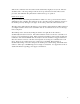
Browsing the Camera’s Web Pages Once communications with the camera has been established, the user can navigate a series of web pages, setting parameters and operational modes. Each page presented by the camera is described in this section. ______________________________________________________________________________________ OBSERVER IV Camera Settings System Settings Operating Mode Network Settings Test and Troubleshoot Take a Picture Colorado-video.com Version 1.
______________________________________________________________________________________ This page sets characteristics of the image delivered by the camera. Exposure - Automatic exposure levels can be made darker or lighter by selecting the Exposure setting. Medium exposure works best in most situations. Quality - This will determine the amount of JPEG compression that is applied to the image. The High quality setting will result in the most image detail and will produce a larger file.
________________________________________________ OBSERVER IV System Settings Enter the current time, date and day of week if different than those shown. Use the same format. Hours are based on a 24-hour clock. Dates are in month-date-year format. Time 1:00 Date 1-1-04 Day Mon Enter the file name for the pictures sent to the server. If Constant File Name is selected, each picture will overwrite the previous one with the given file name.
APN – Access Point Name is a name provided by the cellular service that allows the camera to gain access to the Internet via their network. Contact your cellular service provider for the correct value to enter here. PIN – Some SIM cards require a 4-8 digit ‘personal identification number’. The cellular service provider will supply this number if it is required. If a PIN is not required, leave this field blank.
Image Delivery – Select either Email or FTP delivery of images. All images from the camera will be delivered in this manner. Activation – The camera will always deliver a picture when the external trigger line is brought to ground. Additionally, the camera can be scheduled to deliver a picture based on the day of the week and the time. Check the Enable Schedule box and set the scheduled times on the Schedule page to enable this function.
Which Minutes – This selection determines which minutes will be scheduled. Only quarter hour increments are available. ______________________________________________________________________________________ OBSERVER IV Network Settings Information about the FTP and email servers is entered here. If either FTP or email functions are not utilizied, the corresponding fields may be left blank. If text message notification is enabled enter the receiving cell phone's number.
Email address – This entry must contain the email address of the recipient of the image. Email server – This entry must contain the Internet address of an accessible Email server. Email username – Enter the email username if authorization is enabled on the account. If no authorization is required, this may be left blank. Email password - Enter the email password if authorization is enabled on the email account. If no authorization is required, this may be left blank. Cell phone #.
Modem Configuration/Cellular Service – This test will report the status of the wireless modem and cellular connection. Image Delivery Test – This link will activate the camera and deliver an image according to the current configuration. Notification Test – This link will send a notification message in the manner currently configured. Text Message Reception Test – This link can be used to verify that the camera can receive an text message from a cellular phone.
Checking the “Alert when image refreshed” box will cause an audible annunciation to occur each time a new image is retrieved from the server. The image can be displayed at its original size (Actual Size) or can be sized by the user (Fit to Window). Checking the “Archived Path” box will cause each picture to be saved in a folder specific for that camera. The archive path to these folders can also be defined. If the “Archive Path” is not checked the images will be displayed only and not retained.
Note also that proper operation of the camera with the FTPJPG application requires that the camera be configured to produce images with a ‘constant’ name type. This selection is found on the System Settings page on the camera and must be selected if the FTPJPG application is to be used. Image display The selected images will be displayed and updated. They may be moved and resized as desired.
once a window is closed, it must be reselected on the corresponding server as previously described. The Observer IV camera will continue to deliver images to the FTP server even when the FTPJPG application is not running. However, the most recent image will overwrite the previous one, which will be lost. The only way to save each image delivered by the camera is to have FTPJPG active.
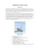
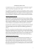
The Camera Case and Controls GSM antenna Weatherproof case Do not remove side screws.
Removing the antenna The antenna may be removed when handling or shipping the camera. Grab the thick, middle part of the mast and unscrew. When replacing, screw down finger tight, do not over-tighten.
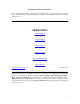
Cellular antennas provided with the Observer. Quad band operation utilizes two different antennas, shown above. The larger whip, on the left, is tuned for 850/1900 MHz operation. The smaller ¼ wave radiator, on the right, is optimized for 900/1800 MHz operation. In areas where sufficient signal strength is present either antenna should function satisfactorily.
Removing the end caps Loosen the bottom screws at the back end one-half turn. Remove the screws holding the clear end cap. Use a small screwdriver or fingernail at the bottom edge to lift out the clear end cap.
Replacing the batteries Remove the four screws holding the bottom plate. Remove the bottom plate Insert batteries with the correct polarity.
The power selection switch Set the internal power selector switch depending on the use of batteries or an external AC adapter. Push the switch up towards the red dot when using internal batteries. Push the switch down away from the red dot when using the external AC adapter.
The back panel Configuration switches Power switch Serial communications port Subscriber Identity Module slot Status LEDs Serial communications port – This port is used to connect the Observer to a desktop PC for configuration and testing. Configuration Switches – These switches are used for configuring and testing the Observer camera. Switch #1 - Forces the camera into configuration mode. This switch must be DOWN to configure the camera and UP for normal operation.
When the power switch is in the AUTO (right) position the camera is normally un-powered. It will turn on in response to an external trigger signal or to a previously scheduled time. Subscriber Identity Module slot – This slot accepts the SIM card supplied by the GSM service provider when a GPRS data account is obtained. Insert the card with the copper contacts down, push all they way in until the locking action is felt.
Power connections An external DC power supply may be connected to pins 1 and 2 of the external connector. Make sure the power supply meets the requirements outlined in Appendix B. When the external power connections are used, the internal power selector switch must be set properly. Do not reverse power supply leads; the camera will be damaged. External trigger operation The external trigger line allows the camera to be activated by an external switch closure (door/gate switch or a motion detector).
The signal provides the return path (- side) for a DC power supply. The signal can sink up to 1.5 amperes at 30 volts DC. Exceeding these limits will damage the unit. The external illuminator must provide its own power supply. The minus side of this power supply is connected to the ‘return’ signal on the camera.
Conclusion The Observer IV is a digital still camera that utilizes the GSM/GPRS cellular phone network to deliver images to any computer on the Internet. The Observer IV can be utilized in a variety of applications; as a wireless solution to unique security problems, as a monitoring system for remote areas, or as a simple way to promote special events via the Internet. The camera has several operating modes and options. A “Quick Start Guide” can be found on the CD.
Appendix A - Rules, Regulations and Safety Concerns FCC rules require that during operation of this type of equipment a minimum separation of 20 cm (8 inches) must be maintained between the antenna and persons. This regulation should be adhered to whenever the camera may be powered on, either in its final installation or during configuration and testing. FCC rules require that the camera be operated only with the supplied antenna. Do not attempt to operate the unit with any other antenna type.
Only the two acrylic end caps and the bottom plate are designed to be removed by the user. Do not attempt to disassemble the camera; there are no user serviceable parts inside All networks, wireless as well as wired, contain some inherent unreliability. The successful delivery of images or notifications at all times cannot be guaranteed. Do not rely on the correct operation of the Observer camera in critical conditions, where life or property may be threatened.
Appendix B - Specifications Enclosure: Weatherproof aluminum case 4.0 x 2.63 x 8.63 inches (WxHxL) ¼ x 20 threaded mount Operating conditions: Temperature -30 to +60 degrees Celsisu (-22-140 F) Humidity up to 95% non-condensing Power requirements: 5 – AA cells internal or 4-15 DC volts external Standby current: 130 ma rms at 5 volts Transmit current: 350 ma rms at 5 volts (850 ma rms peak) Camera: ¼ CMOS image sensor @640 x 480 or 320 x 240 resolution Lens options: 4.5 mm 6.0 mm 12.
Appendix C - Power Supply Considerations and Power Switch Settings The camera can be powered externally with an AC adapter or internally via 5 AA batteries. Internal batteries Remove the four machine screws holding the bottom plate to access this area. When internal batteries are used, the switch on the battery tray must be in the upward (towards the red dot) position. Make sure the batteries are installed with the correct polarity, the flat end of the battery (negative) faces the spring within the holder.
Power mode (switch position) ON (left) AUTO (right) Generally powered from Internal power selector Normal powered state Trigger and schedule modes? Notification available? Continuous mode available? Will respond to cell phone commands? External connection Away from red dot Always on Yes Yes Yes Yes Internal batteries Towards red dot Mostly off Yes Yes No No Note that the table illustrates the most likely use of the two available power modes.
Appendix D - Establishing Communications with Different Operating Systems A utility is available which will automatically configure a desktop computer to communicate with the Observer IV camera. This “InstallObserver” utility operates on computers using the Windows 2000 or Windows XP operating system. This utility is described in Appendix G of this manual. When using a computer with the Windows 98 SE operating system, the communications link must be established by following the directions below.
5) Select I want to set up my Internet connection manually or I want to connect through a local area network (LAN) and press Next. 6) Select I connect through a phone line and a modem and press Next. 7) Select the Standard 57600 modem just installed. (This step will be skipped, if this is the only modem currently installed on this computer.) 8) The Observer Camera does not need a telephone number. However, Windows 2000 requires at least a single digit to be entered. Enter any number(s) for the phone number.
14) From Control Panel, click Network Connections, then click Create a new connection. Press Next. 15) Select Connect to the Internet and press Next. 16) Select Set up my connection manually and press Next. 17) Select Connect using a dial-up modem and press Next. 18) Select the modem created above (Standard 57600 bps Modem…). Click Next. 19) Name the connection “Observer Camera” and click Next. 20) Enter any number in the Phone number field (the Observer Camera does not use this) and click Next.
22) Make sure that Use default gateway on remote network is the only other option selected and press OK. 23) You have now successfully created the connection for the Observer Camera. 24) Right click the newly created icon on the Dial-Up Networking page and select Create Shortcut. Answer Yes to the question Do you want the shortcut placed on the Desktop. 25) Once the Observer is properly connected to the COM port and turned on, clicking on this icon will establish communications.
Appendix E - Test and Troubleshoot A series of tests are available to insure proper camera operation. First establish communications with the camera via a desktop PC and a web browser. Configure the camera as desired. Next select the Test and Troubleshoot link on the home page to display the available tests. Execute the tests and inspect the displayed results to verify operation or to find and resolve problems. The following pages detail the expected results for each test.
FILE TRANSFER TEST PASSED BACK Starting image...image acquired Registering modem...**..modem attached. Establishing GPRS connection.....GPRS connection established.....FTP server reached. 220 LinusJr FTP server (Version wu-2.6.2-5) ready. USER anonymous This is the FTP oaccount user name 331 Guest login ok, send your complete e-mail address as password. PASS embedded@earthlink.net Here is the 230 Guest login ok, access restrictions account password. apply TYPE I 200 Type set to I.
SMTP: Read: 250 sender "mypictures@attws.net" OK SMTP: Wrote RCPT TO: "embeddedsys@earthlink.net" SMTP: Read: 250 recipient "embeddedsys@earthlink.net" OK SMTP: Wrote DATA SMTP: Read: 354 Enter mail, end with "." on a line by itself SMTP: Wrote From: "mypictures@attws.net" To: "embeddedsys@earthlink.net" Subject: Transfering email * SMTP: Wrote ************************* SMTP: Message finished SMTP: Wrote . SMTP: Read: 250 Message received and queued SMTP: Wrote QUIT SMTP: Read: 221 Until later [10.112.187.
SMTP: Wrote MAIL FROM: "mypictures@attws.net" SMTP: Read: 250 sender "mypictures@attws.net" OK SMTP: Wrote RCPT TO: "embeddedsys@earthlink.net" SMTP: Read: 250 recipient "embeddedsys@earthlink.net" OK SMTP: Wrote DATA SMTP: Read: 354 Enter mail, end with "." on a line by itself SMTP: Wrote From: "mypictures@attws.net" To: "embeddedsys@earthlink.net" Subject: Transfering email * SMTP: Wrote SMTP: Message finished SMTP: Wrote .
Appendix F - Network Services and Cell Phone Access Email servers Computers on the Internet that handle email are called SMTP servers (Simple Mail Transfer Protocol). To send email, the Observer camera needs access to an SMTP server. Usually SMTP servers provided to the customers of common Internet Service Providers (ISP's) such as AOL, MSN, or Earthlink restrict access to their servers only to account holders associated with the ISP.
Cell Phone Access The Observer camera can interact with a cell phone via text messaging. Notification of external trigger events will be sent to a cell phone, when enabled. The destination cell phone number for notification is defined on the Network Settings page within the Observer. Selecting text messaging as the notification type on the Operating Mode page will enable this function.
Appendix G - Using the InstallObserver Utility This utility will configure a desktop computer to make a connection with its serial port to the Observer Camera. This utility only sets the parameters for the connection, it does not actually establish the link with the camera. First, select an unused serial port on the back of the computer (also referred to as a COM port). Inspect the back of the computer for a spare 9 pin serial port, probably labeled COM1 or COM2.
11) This will bring you back to the original “Phone and Modem Options” window. It should now display only the 56000 bps modem installed on the selected COM port. If not, return to step 2 and remove all modem drivers installed on the selected COM port, and continue from that step. If only the 56000 bps modem is shown on the selected port, click ‘OK’. 12) This completes the first half of the installation process.
Appendix H - GSM, SIM, PIN and the Observer Camera The GSM cellular network (Global System for Mobile communications) is the most prevalent cellular network in the world. In order to access this network with the Observer camera a SIM (Subscriber Identity Module) card is required. This small plastic card is the same as used in cellular phones. It contains the account information and stored phone numbers and text messages.
It’s worth noting here that the Modem Configuration/Cellular Service test will also display the phone number associated with the SIM card. Each SIM account has an associated phone number, even if it is a ‘data only’ SIM. This number is the one to use to send text messages to the camera if the ‘continuous mode’ of operation is to be used. Not all providers will program the SIM card with the account phone number.
Appendix I – Observer Accessories The following items, designed to work with the Observer IV camera, are available from the dealer. Additional lenses The Observer camera can support a variety of fixed focus telephoto and wide-angle lenses Solar power supply The Observer camera can be powered indefinitely from a solar panel based power supply. AC adapter AC adapters allow operation from AC mains supply.