
Installation Manual

ENFORCER One- and Two-Channel 917MHz RF Receivers
2 SECO-LARM U.S.A., Inc.
Each c
hannel
relay
can be programmed to
one of five
output
modes
.
(
HL
-
9
5
1R2
-
x
Q
only:
E
ach
channel
can be
independently programmed to operate in a different output mode, depending on the user’s application.) The five modes are:
1. P1 – 1~99 Second Timed Pulse Output (default, 1 second) – When the transmitter button is pressed, the relay will turn
ON for the programmed number of seconds.
2. P2 – Toggle Output – Works much like a toggle switch to turn a device ON & OFF alternately. Press the transmitter
button once, and the relay turns ON. Press the transmitter button again, and the relay turns OFF.
3. P3 – Latch Output – Press the transmitter button once, and the relay turns ON and stays ON. The channel relay will
remain ON regardless of whether a compatible transmitter button is pressed again or not. To turn the relay OFF, press
the selector switch on the receiver once to reset.
4. P4 – Validity Output – The channel will turn the relay ON for as long as the transmitter button is pressed.
NOTE: Due to possible interference or drops in transmitter battery power while the transmitter button is continuously
pressed (even for short periods of time), the receiver may lose the transmitter’s signal and turn the relay OFF.
5. P5 – 1~99 Minute Timed Pulse Output – When the transmitter button is pressed, the relay will turn ON for 1 second.
Clear Channel Memory:
1.
Enter programming mode and select the desired channel as described on pg.
1.
2. While the LED is flashing, press the selector button again for at least 3 seconds or until the channel indicator LED
flashes 3 times. This will clear all codes for that channel.
3. To clear codes from the other channel, enter programming mode for the other channel and repeat the above steps.
Display Channel Memory:
1.
To see how many codes have been learned
by
a channel, enter programming mode and select the desired channel as
described on pg. 1.
2. The LED will flash for 15 seconds showing number of codes stored in that channel’s memory.
Programming Channel Relay Output
Mode
:
Selecting the relay output
mode
:
• Enter programming mode and select the desired
channel as described on pg. 1.
• Press the selection button again. The LED will
display the current output mode (default P1).
• To change a channel’s output mode, press the
selector button repeatedly to scroll through the 5
output modes until the desire mode appears. Each
press moves to the next mode in the sequence as
shown in the diagram to the right.
• In modes P1 and P5, long press the selector button
to choose the number of seconds or minutes,
respectively
• When complete, wait 15 seconds for the receiver to
automatically exit programming mode.
NOTE:
For a diagram of the PC board, including the location of
the function switch, please see Overview, pg. 3.
Toggle Output
(P2)
Validity Output
(P4)
1~99 sec (default, sec)
Timed Pulse Output
(P1)
Latch Output
(P3)
1~99 min
Timed
Pulse
Output
(
P5
)
Code Learning a New Transmitter Button:
1.
Enter programming mode and select the desired channel as described on pg.
1.
2. While the LED is flashing, press the desired transmitter button to be learned one time. The three horizontal bars of the
receiver’s LED indicator will flash three times to indicate the transmitter button has been successfully learned and will
automatically exit learning mode. To learn further codes, re-enter programming mode and repeat.
NOTES:
• Do not press the selection button again after entering programming mode as this will take you to output mode
programming.
• The indicator LED will flash a maximum of 15 seconds. If no transmitter button is pressed during this time, the receiver
will exit code programming mode, and the LED will turn off.
• If the code has already been learned, the indicator LED will slowly flash two dashes. The code will not be learned a
second time.
• One channel can learn the codes of a maximum of 99 transmitter buttons. If you attempt to learn an additional transmitter
code, the earliest code learned will be deleted and the new code will be learned.
ENFORCER One- and Two-Channel 917MHz RF Receivers
SECO-LARM U.S.A., Inc. 3
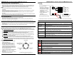
SK-910RB2Q shown. SK-910RBQ is the
same, but only has one each: mode
switch; function switch; indicator LED;
channel relay.
Selector Button
Operation
:
LED Indicat
or
:
Overview:
HL-951R2-SQ PC board shown. Remove the front cover of the receiver to access the function switch and terminal block.
Enter programming
mode
Press and hold
the selector button for three seconds or more
to enter programming mode.
Select channel for
programming
E
ntering progr
amming mode automatically takes you to channel 1. To select channel 2,
press the
selector button once more.
Learn code
After e
nter
ing
programming mode for the desired channel
, the receiver is ready to learn a code,
so the selector button is not used again. To learn a code press the desired button on the
transmitter.
Delete all codes
from a channel
After entering programming mode for the desired channel,
wait until the LED begins to flash a
number (the number of codes learned for that channel), then press and hold the selector button
for at least three seconds or until the LED flashes 3 stripes.
Memory display
After entering programming mode for the desi
red channel, after 2 seconds the LED will begin to
flash a number indicating the number of codes already stored for that channel.
Programming output
mode
After entering programming mode for the desired channel, press the selector button again. The
display will show the current mode (P1~P5). To change the mode, press again repeatedly until
the display shows the desired mode.
Programming timed
pulse duration
After following the above steps to program the output mode, when in mode P1 or P5, long press
the selector button to change the number of seconds or minutes, respectively.
8. 8.
Flashing every 3~5 seconds – receiver powered on and in operation
8. 8.
A valid RF signal has been received
L.1.
Flashing – number shows current channel to be programmed
=. =.
Flash 2 times – new code has been learned or all codes for that channel have been deleted
-
.
-
.
Slow flashing – in programming mode, shows that the attempted code has previously been learned
Flash 2 times – exit programming mode
0. 0.
F
lashing
–
in programming
mode, shows the number of codes (0~99) already learned for the selected
channel
P.1.
In output programming mode – number indicates the current mode
0.1.
In output programming mode when either P1 or P5 has been selected
–
number indicates the output time
in
seconds or minutes, respectively
See "Selector Button Operation,"
below for a description of the
various uses of this button
Selector
Button
Power input
Ch 1 relay
N.O.1
N.C.1
COM1
N.O.2
N.C.2
COM2
Ch 2 relay
– VAC1
+
VAC2
LED Display
(
HL
-
915
R2
-
x
Q
only
)
8. 8.
The LED indicator displays
:
• General status – the left dot will
flash every 3~5 when operating
• RF signal received – the right dot
will light when an RF signal is
being received
• TX Code enrollment and deletion
• Display number of codes
programmed
• Output mode programming
See "LED Indicator" below for details.