
User manual


16
SP ENGBO MAXI 31 32 33 34 40 43 44 Rev3.2July_2014
Installation
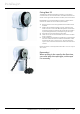
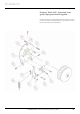
Fitting Maxi 34-D
The Maxi 34-D is designed for horizontal installation on the fore
or aft deck.
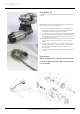
Note! Make sure to t the windlass correctly in relation to the
direction of rotation of the line wheel. (See sketch)
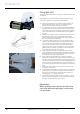
1. Start by locating the correct position for the windlass, so
that the direction of the rope is in line with the anchor
bracket. Then mark the centre of the windlass.
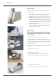
2. In most cases, it is easy to use the windlass xing plate as a
template. Remove the white plastic cover and remove the
line wheel, rope guides and spring so that the xing plate is
“clean”. Remove the six screws that hold the xing plate to
the gear.
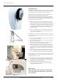
3. Place the xing plate on the boat and mark the screw holes,
the centre hole for the gear, the hole for the auto stop
switch (on the front port side edge of the xing plate), and
the run-through hole for the rope.
4. The easiest way to position the run-through hole for the
rope is to drill the tting holes for the xing plate and then
use a couple of screws to fasten this plate temporarily to
the boat. Put the plastic cover on and mark the forward
edge of the cover on the contact surface. Use an appropri-
ate hole-cutter and make sure that the cover overlaps the
outer edge of the hole by around 5 mm.
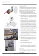
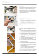
5. Then make the holes with an appropriate drill and hole-
cutter. Remember to sand the upper aft edge and the lower
fore edge of the run-through hole for the rope, to prevent
the rope from catching on sharp edges.
6. Then screw the xing plate rmly in place on the boat.
Remember to draw the auto stop switch from the front port
side hole of the xing plate before screwing the gear rmly
in place. To prevent the rope becoming entangled with the
motor on the inside of the boat, t the gear so that the mo-
tor is pointing directly forward, facing the port or starboard
side.
7. Then t the anchor bracket and check that the anchor t
correctly on the rollers.
8. Fit the sheaves and covers, the rope guard, the rope guide
and the spring. Then t the auto stop switch in the hole in
the rope guard and adjust it so that the sensor face pro-
trudes approx. 1 mm towards the rope.
9. Then pull the rope through the hole in the cover, run it be-
tween the line wheel and the rope guide and down below
the deck. Finally, fasten the cover in place.
Remember!
When pulling in the rope for the rst time,
you must keep the rope tight, so the rope
run correctly.