
User manual

21
SP ENGBO MAXI 31 32 33 34 40 43 44 Rev3.2July_2014
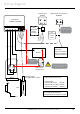
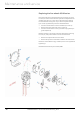
BAT
AUX
1
2
3 4
D1 D2A2 B-
BATTERY
+
-
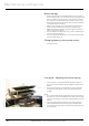
Control box
14-0604 / 14-0604C
Opt.
Side-power
remote
receiver
Control panel
8950W
brown
blue
Autostop Sensor
(Not applicable for chain)
Main circuit
brea ker/fuse
D1
D2
A1A2
(Alternative control panel)
86-00002
Motor
4-lead
Sidepower
control cable
Connection to
control box :
white to terminal 2
green to terminal 3
brown to terminal 4
1,5 mm2
A
B
C D E F
Cab le size A,B,C,D,E and F :
If total length
A+B+C+D+E+F <6m : 25mm2
A+B+C+D+E+F=6-16m : 35mm2
A+B+C+D+E+F>16m : 50mm2
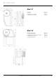
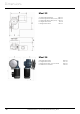
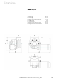
Maxi
To change motor direction:
Change cables D1 and D2 on motor
Power supply cable for PCB
and relay
For installation of panel 86-
00002, se own manual
Wiring diagram
Important!
Cable B must go from AUX
to A1 on motor