11N Long Range Multi-Function Gigabit Client Bridge ECB350 11N Long Range Multi-Function Gigabit Client Bridge V1.
1 Table of Contents 1 Introduction ..................................................................................................................................................................5 1.1 1.2 1.3 1.4 2 Before you Begin .........................................................................................................................................................8 2.1 2.2 2.3 2.4 3 Save/Reload ........................................................................................
2 6.1.3 6.1.4 6.2 6.3 6.4 6.5 6.6 6.7 6.8 6.9 7 Wireless ......................................................................................................................................................................48 7.1 7.2 7.3 7.4 7.5 7.6 7.7 8 Wireless Network ..................................................................................................................................................48 Wireless Security .....................................................................
3 9.1 9.2 9.3 9.4 9.5 Client Bridge Mode ...............................................................................................................................................78 Access Point Mode ...............................................................................................................................................78 Access Point Mode with WDS Function (WDS AP mode).....................................................................................80 WDS Bridge Mode .......
4 Revision History Version 1.
5 1 Introduction The ECB350 is a multi-functioned 802.11b/g/n product with 8 major multi-functions. It is designed to operate in every working environment for enterprises. The ECB350 is a Wireless Network device that delivers up to 6x faster speeds and 7x extended coverage than 802.11b/g devices. The ECB350 supports use in the home network with superior throughput, performance, and unparalleled wireless range.
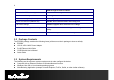
6 SSID through the built in software. WPA2/WPA/ IEEE 802.1x support Powerful data security. MAC address filtering in AP mode Ensuring secure network connection. User isolation support (AP mode) Protecting the private network between client users. Power-over-Ethernet (IEEE802.3af) Flexible Access Point locations and saving cost. Save User Settings Firmware upgrade does not delete user settings. SNMP Remote Configuration Management Allows remote connection to configure or manage the ECB350 easily.
7 1.4 Applications The wireless LAN products are easy to install and highly efficient. The following list describes some of the many applications made possible through the power and flexibility of wireless LANs: a) Difficult-to-Wire Environments There are many situations where wires cannot be laid easily. Historic buildings, older buildings, multiple buildings, and/or open areas make the installation of a Wired LAN impossible, impractical, and/or expensive.
8 2 Before you Begin This section will guide you through the installation process. Placement of the ENGENIUS ECB350 is very important to maximize the ECB350’s performance. Avoid placing the ECB350 in an enclosed space such as a closet, cabinet, or wardrobe. 2.1 Considerations for Wireless Installation The operating distance of all wireless devices cannot be pre-determined due to a number of unknown obstacles in the environment that the device is deployed. in.
9 2.2 Computer Settings (Windows XP/Windows 7) In order to use the ECB350, you must first configure the TCP/IPv4 connection of your computer system. Click Start button and open Control Panel.
10 In Windows XP, click Network Connections In Windows 7, click View Network Status and Tasks in the Network and Internet section, then select Change adapter settings Right click on Local Area Connection and select Properties Select “Internet Protocol Version 4 (TCP/IPv4)” and select Properties
11 Select Use the following IP address and enter IP address and subnet mask then click OK. Note: Ensure that the IP address and subnet mask are on the same subnet as the device. For example: Device IP address: 192.168.1.1 PC IP address: 192.168.1.2 – 192.168.1.254 PC subnet mask: 255.255.255.
12 2.3 Apple Mac X OS Go to System Preferences (can be opened in the Applications folder or selecting it in the Apple Menu) Select Network in the Internet & Network section Highlight Ethernet In Configure IPv4, select Manually Enter IP address and subnet mask then press OK Note: Ensure that the IP address and subnet mask are on the same subnet as the device. For example: Device IP address: 192.168.1.1 PC IP address: 192.168.1.2 – 192.168.1.254 PC subnet mask: 255.255.255.
13 2.4 Hardware Installation 1. Ensure that the computer in use has an Ethernet Card (RJ-45 Ethernet Port). For more information, verify with our computer user manual. 2. Connect one end of the Category 5 Ethernet cable into RJ-45 port of the ECB350 and the other end to the RJ-45 port on the computer that will use the ECB350. Ensure that the cable is securely connected to both the ECB350 and the Computer. 3.
14 Front Panel Rear Panel Front Panel LED Lights LED lights for Wireless, Ethernet port and Power. Rear Panel DC IN DC IN for Power. Reset Button One click for reset the device. Press over 10 seconds for reset to factory default. Ethernet Port Ethernet port for RJ-45 cable.
15 3 Configuring Your Client Bridge This section will show you how to configure the device using the web-based configuration interface. 3.1 Default Settings Please use your Ethernet port or wireless network adapter to connect the Client Bridge. Default Settings IP Address 192.168.1.
16 3.2 Web Configuration Open a web browser (Internet Explorer/Firefox/Safari) and enter the IP Address http://192.168.1.1 The default username and password are admin. Once you have entered the correct username and password, click the Login button to open the web-base configuration page. If successful, you will see the ECB350 User Menu. Note: If you have changed the default LAN IP Address of the Access Point, ensure you enter the correct IP Address.
17
18 4 Status The Status section contains the following options: Main, Wireless Client List and System Log. The following sections describe these options. 4.1 Save/Reload This page lets you save and apply the settings shown under Unsaved changes list, or cancel the unsaved changes and revert to the previous settings that were in effect.
19 4.2 Main Clicking the Main link under the Status menu or clicking Home at the top-right of the Web Configurator shows status information about the current operating mode. - The System Information section shows general system information such as device name, MAC address, current time, firmware version and management VLAN ID (Note: VLAN ID is only in Access Point and WDS AP mode). - The LAN Settings section shows Local Area Network setting such as the LAN IP address, subnet mask, and DNS address.
20 - The Current Wireless Settings section shows wireless information such as operating mode, frequency and channel. Since the ECB350 supports multiple-SSIDs, information about each SSID, such as its ESSID and security settings, are displayed (Note: Profile Settings is only in Access Point, WDS AP and Router mode).
21 4.3 Connection Status Click on the Connection Status link under the Status menu. This page displays the current status of the network, including Network Type, SSID, BSSID, Connection Status, Wireless Mode, Current Channel, Security, Data Rate, Noise Level and Signal Strength. Note: Only in Client Bridge, Client Router, WDS Station and Repeater mode.
22 4.4 Wireless Client List Clicking the Wireless Client List link under the Status menu displays the list of clients associated to the ECB350, along with the MAC addresses and signal strength for each client. Clicking the [Refresh] button updates (refreshes) the client list. Note: Only in Access Point, WDS AP, Repeater and Router mode.
23 4.5 System Log The ECB350 automatically logs (records) events of possible interest in its internal memory. To view the logged information, click the System Log link under the Status menu. If there is not enough internal memory to log all events, older events are deleted from the log. When powered down or rebooted, the log will be cleared. System Log Refresh Update the log. Clear Clear the log.
24 5 System 5.1 Operation Mode The ECB350 supports 8 operating modes: Access Point, Client Bridge, WDS AP, WDS Bridge, WDS Station, Universal Repeater, Router and Client Router. System Properties Device Name Enter a name for the device. The name you type appears in SNMP management. This name is not the SSID and is not broadcast to other devices. Operation Mode Use the radio button to select an operating mode.
25 5.2 IP Settings This page allows you to modify the device's IP settings. Note: Only in Access Point, Client Bridge, WDS AP, WDS Bridge, WDS Station and Repeater mode. IP Settings IP Network Setting Select whether the device IP address will use the static IP address specified in the IP Address field or be obtained automatically when the device connects to a DHCP server. IP Address The IP Address of this device. IP Subnet Mask The IP Subnet Mask of this device.
26 5.3 Spanning Tree Setting This page allows you to modify the Spanning Tree settings. Enabling Spanning Tree protocol will prevent network loops in your LAN network. Note: Only in Access Point, Client Bridge, WDS AP, WDS Bridge, WDS Station and Repeater mode. Spanning Tree Spanning Tree Status Enable or disable the Spanning Tree function. Bridge Hello Time Specify Bridge Hello Time, in seconds.
27 Priority Specify the Priority number. Smaller number has greater priority. Accept / Cancel Click [Accept] to confirm the changes or [Cancel] to cancel and return previous settings.
28 6 Router This section is only available for AP Router Mode and Client Router Mode. 6.1 WAN Settings There are four types of WAN connections: Static IP, DHCP, PPPoE and PPTP. Please contact your ISP to find out which settings you should choose. 6.1.1 Static IP If your ISP Provider has assigned you a fixed IP address, enter the assigned IP address, Subnet mask, Default Gateway IP address, and Primary DNS and Secondary DNS (if available) of your ISP provider.
29
30 Static IP Internet Connection Type Select Static IP to begin configuration of the Static IP connection. Account Name Enter the account name provided by your ISP. Domain Name Enter the domain name provided by your ISP. MTU Specify the Maximum Transmit Unit size. It is recommended you accept the default setting of Auto. Otherwise, packets will be fragmented downstream if the MTU is set too high or too low, which impacts network performance.
31 6.1.2 DHCP Select DHCP as your WAN connection type to obtain an IP address automatically. You will need to enter account name as your hostname and, optionally, DNS information.
32 Internet Connection Type Select DHCP to begin configuration of the DHCP connection. Account Name Enter the account name provided by your ISP. Domain Name Enter the domain name provided by your ISP. MTU Specify the Maximum Transmit Unit size. It is recommended you accept the default setting of Auto. Otherwise, packets will be fragmented downstream if the MTU is set too high or too low, which impacts network performance.
33 6.1.3 PPPoE Select Point to Point Protocol over Ethernet (PPPoE) if your ISP uses a PPPoE connection. Your ISP will provide you with a username and password. This selection is typically used for DSL services. Remove your PPPoE software from your computer, as it is not needed and will not work with your ECB350.
34 Internet Connection Type Select PPPoE to begin configuration of the PPPoE connection. MTU Specify the Maximum Transmit Unit size. It is recommended you accept the default setting of Auto. Otherwise, packets will be fragmented downstream if the MTU is set too high or too low, which impacts network performance. In extreme cases, an MTU setting that is too low can prevent the ECB350 from establishing some connections. Login Enter the Username provided by your ISP.
35 6.1.4 PPTP Select PPTP as your WAN connection type if your ISP uses a Point-to-Point-Tunneling Protocol (PPTP) connection. You will need to provide the IP address, subnet mask, default gateway (optional), DNS (optional), server IP, username, and password provided by your ISP.
36 Internet Connection Type Select PPTP to begin configuration of the PPTP connection. MTU Specify the Maximum Transmit Unit size. It is recommended you accept the default setting of Auto. Otherwise, packets will be fragmented downstream if the MTU is set too high or too low, which impacts network performance. In extreme cases, an MTU setting that is too low can prevent the ECB350 from establishing some connections. IP Address Enter the WAN port IP address. Subnet Mask Enter the WAN IP subnet mask.
37 6.2 LAN Settings This page allows you to modify the device's LAN settings. LAN Settings IP Address The LAN IP Address of this device. IP Subnet Mask The LAN Subnet Mask of this device. Use Router As DHCP Server Check this option to enable the internal DHCP server. Starting /Ending IP Address The range of IP addresses of the DHCP server will allocate to LAN device. WINS Server IP Enter the IP address of the WINS server.
38 6.3 VPN Pass Through VPN Passthrough allows a secure virtual private network (VPN) connection between two computers. Enabling the options on this page opens a VPN port and enables connections to pass through the ECB350 without interruption.
39 6.4 Port Forwarding Port forwarding can be used to open a port or range of ports to a device on your network. Using port forwarding, you can set up public services on your network. When users from the Internet make certain requests on your network, the ECB350 can forward those requests to computers equipped to handle the requests. If, for example, you set the port number 80 (HTTP) to be forwarded to IP address 192.168.1.150, all HTTP requests from outside users are forwarded to 192.168.1.150.
40 Port Forwarding Port Forwarding Enables or disables the Port Forwarding feature. Service Name Enter a name or description to help you identify this entry. Protocol Select a protocol for the application. Choices are Both, TCP, and UDP. Start / End Port The port range that the server is running on the local computer. IP Address The local IP address of the computer the server is hosted on.
41 6.5 Port Triggering If you use Internet applications which use non-standard connections or port numbers, you may find that they do not function correctly because they are blocked by the device’s firewall. Port Triggering will be required for these applications to work.
42 Port Triggering Port Triggering Enables or disables the Port Triggering feature. Service Name Enter a name or description to help you identify this entry. Trigger Port This is the outgoing (outbound) port numbers for this application. Trigger Type Select whether the application uses TCP, UDP or Both types of protocols for outbound transmissions. Forwarded Port These are the inbound (incoming) ports for this application.
43 6.6 DMZ If you have a computer that cannot run Internet applications properly from behind the ECB350, you can allow the computer to have unrestricted Internet access. Enter the IP address of that computer as a Demilitarized Zone (DMZ) host with unrestricted Internet access. Adding a client to the DMZ may expose that computer to a variety of security risks, so use this option as a last resort. DMZ DMZ Hosting Enables or disables the DMZ function.
44 6.7 MAC Filter You can choose whether to Deny or Allow only those devices listed in the MAC Filtering table to access the Internet. MAC Filter MAC Filter Enables or disables the MAC Filter function. Deny all clients with MAC addresses listed below to access the network When selected, the computers listed in the MAC Filter table will be Denied to access the Internet.
45 6.8 IP Filter You can choose whether to Deny or Allow only devices with those IP Addresses listed on the IP Filter Table from accessing certain ports. This can be used to control which Internet applications the computers can access. Note: You will need to have knowledge of what Internet port numbers each application uses.
46 IP Filter Enables or disables the IP Filter function. Deny all clients with IP addresses listed below to access the network When selected, the computers listed in the IP Filter table will be Denied to access the Internet. Allow all clients with IP addresses listed below to access the network When selected, only the computers listed in the IP Filter table will be Allowed to access the Internet.
47 6.9 URL Filter You can deny access to certain websites by blocking keywords in the URL web address. For example, “gamer” has been added to the URL Filter Table. Any web address that includes “gamer” will be blocked.
48 7 Wireless 7.1 Wireless Network This page shows the current status of the device's Wireless settings.
49 Wireless Network (Access Point / WDS AP / Router mode) Wireless Mode Wireless mode supports 802.11b/g/n mixed mode. Channel HT Mode The default channel bandwidth is 20/40MHz. The larger the channel, the better the transmission quality and speed. Extension Channel Select upper or lower channel. Your selection may affect the Auto channel function. Channel / Frequency Select the channel and frequency appropriate for your country’s regulation. Auto Check this option to enable auto-channel selection.
50 SSID Profile SSID Specify the SSID for the current profile. VLAN ID Specify the VLAN tag for the current profile. Suppressed SSID Check this option to hide the SSID from clients. If checked, the SSID will not appear in the site survey. Station Separation Click the appropriate radio button to allow or prevent communication between client devices. Wireless Security See the Wireless Security section.
51 Wireless Network (Client Bridge / Client Router / WDS Station / Repeater mode) Wireless Mode Wireless mode supports 802.11b/g/n mixed mode. SSID The SSID is a unique named shared amongst all the points of the wireless network. The SSID must be identical on all points of the wireless network and cannot exceed 32 characters. You may specify an SSID or select one from the Site Survey. Site Survey Click on Site Survey to search the existing Access Points.
52 7.2 Wireless Security The Wireless Security section lets you configure the ECB350's security modes: WEP, WPA-PSK, WPA2-PSK, WPA-PSK Mixed, WPA, WPA2, and WPA Mixed. We strongly recommend you use WPA2-PSK. WEP Encryption: WEP Encryption Auth Type Select Open System or Shared Key. Input type ASCII: regular text (recommended) HEX: for advanced users Key Length Select the desired option, and ensure the wireless clients use the same setting. Choices are 64, 128, 152-bit password lengths.
53 others are optional. WPA-PSK (WPA Pre-Shared Key) Encryption: WPA-PSK (WPA Pre-Shared Key) Encryption Encryption Select the WPA encryption you would like. Please ensure that your wireless clients use the same settings. Passphrase Wireless clients must use the same key to associate the device. If using passphrase format, the Key must be from 8 to 63 characters in length. Group Key Update Interval Specify how often, in seconds, the group key changes.
54 WPA Encryption Encryption Select the WPA encryption you would like. Please ensure that your wireless clients use the same settings. Radius Server Enter the IP address of the Radius Server Radius Port Enter the port number used for connections to the Radius server. Radius Secret Enter the secret required to connect to the Radius server. Group Key Update Interval Specify how often, in seconds, the group key changes. Note: 802.11n does not allow WEP/WPA-PSK TKIP/WPA2-PSK TKIP security mode.
55 7.3 Site Survey Use this feature to scan nearby Access Points. Note: Only in Client Bridge, Client Router and Repeater mode. 1. Click Site Survey. 2.
56 3.
57 BSSID Access Point's wireless MAC address. SSID SSID that the Access Point is broadcasting. Channel Channel that the Access Point is using. Signal Level (dBm) Signal strength from the Access Point to your station. Type The band that the Access Point is using. Security Encryption method that the Access Point is using to secure data over the WLAN. Refresh Click Refresh to rescan nearby Access Point. 4. Select an Access Point and click that Access Point’s BSSID. 5.
58
59 7.4 Wireless MAC Filter Wireless MAC Filters are used to allow or deny network access to wireless clients according to their MAC addresses. You can manually add a MAC address to restrict the permission to access ECB350. The default setting is Disable Wireless MAC Filter. Note: Only in Access Point, WDS AP and Router mode.
60 7.5 Wireless Advanced This page allows you to configure wireless advance settings. It is recommended the default settings are used unless the user has experience with these functions.
61 Data Rate Select a data rate from the drop-down list. The data rate affects throughput. If you select a low data rate value, for example, the throughput is reduced but the transmission distance increases. RTS/CTS Threshold Specify the threshold package size for RTC/CTS. A small number causes RTS/CTS packets to be sent more often and consumes more bandwidth. Distance Specify the distance between Access Points and clients. Longer distances may drop high-speed connections.
62 7.6 WPS (Wi-Fi Protected Setup) WPS feature is following the Wi-Fi Alliance WPS standard and it eases the set up of security-enabled Wi-Fi networks in the home and small office environment. It reduces the user steps required to configure a network and supports two methods that are familiar to most consumers to configure a network and enable security. Note: Only in Access Point, WDS AP and Router mode.
63 WPS Select Enable or Disable the WPS feature. WPS Current Status Shows whether the WPS function is Configured or unConfigured. Configured means that WPS has been used to authorize connection between the device and wireless clients. Self Pin Code The PIN code of this device. SSID The SSID (wireless network name) used when connecting using WPS. Authentication Mode Shows the encryption method used by the WPS process.
64 7.7 WDS Link Settings Using WDS (Wireless Distribution System) to connect Access Point wirelessly, and in doing so extend a wired infrastructure to locations where cabling is not possible or inefficient to implement. Note that compatibility between different brands and models is not guaranteed. It is recommended that the WDS network be created using the same models for maximum compatibility. Also note that all Access Points in the WDS network needs to use the same Channel and Security settings.
65 Mode Select Disable or Enable from the drop-down list. Accept / Cancel Click [Accept] to confirm the changes or [Cancel] to cancel and return previous settings.
66 8 Management 8.1 Administration This page allows you to change the system password and to configure remote access. By default, the user name is admin and the password is: admin. Password can contain 0 to 12 alphanumeric characters and are case sensitive. Note: Remote Access is only in AP Router and Client Router mode. Change Password Name Enter a new username for logging in to the Web Configurator. Password Enter a new password for logging in to the Web Configurator.
67 8.2 Management VLAN This page allows you to assign a VLAN tag to the packets. A VLAN is a group of computers on a network whose software has been configured so that they behave as if they were on a separate Local Area Network (LAN). Computers on VLAN do not have to be physically located next to one another on the LAN. Note: Only in Access Point and WDS AP mode.
68 8.3 SNMP Settings This page allows you to assign the contact details, location, community name and trap settings for SNMP. This is a networking management protocol used to monitor network-attached devices. SNMP allows messages (called protocol data units) to be sent to various parts of a network. Upon receiving these messages, SNMP-compatible devices (called agents) return data stored in their Management Information Bases. SNMP SNMP Enable/Disable Enable or disable SNMP feature.
69 Trap Trap Destination Address Specify the IP address of the computer that will receive the SNMP traps. Trap Destination Community Name Specify the password for the SNMP trap community.
70 8.4 Backup/Restore This page allows you to save the current device configurations. When you save the configurations, you also can re-load the saved configurations into the device through the [Restore Saved Settings from A File]. If extreme problems occur you can use the [Revert to Factory Default Settings] to set all configurations to its original default settings. Backup/Restore Save A Copy of Current Settings Click [Backup] to save the current configured settings.
71 8.5 Firmware Upgrade This page allows you to upgrade the device's firmware. To perform the Firmware Upgrade: 1. Click the [Browse] button and navigate to the location of the upgrade file. 2. Select the upgrade file. Its name will appear in the Upgrade File field. 3. Click the [Upload] button to commence the firmware upgrade. Note: The device is unavailable during the upgrade process, and must restart when the upgrade is completed. Any connections to or through the device will be lost.
72 8.6 Time Setting This page allows you to set the system time. Time Manually Set Date and Time Manually specify the date and time. Automatically Get Date and Time Select a time zone from the drop-down list and check whether you want to enter the IP address of an NTP server or use the default NTP server.
73 8.7 Log This page allows you to setup Syslog and local log functions. Log Syslog Enable or disable the syslog function. Log Server IP Address Enter the IP address of the log server. Local Log Enable or disable the local log service. Save/Apply / Cancel Click Save/Apply to apply the changes or Cancel to return previous settings.
74 8.8 Diagnosis This page allows you to ascertain connection quality and trace the routing table to the target. Diagnosis Target IP Enter the IP address you would like to search. Ping Packet Size Enter the packet size of each ping. Number of Pings Enter the number of times you want to ping. Start Ping Click [Start Ping] to begin pinging. Traceroute Target Enter an IP address or domain name you want to trace. Start Traceroute Click [Start Traceroute] to begin the trace route operation.
75 8.9 LED Control This page allows you to control LED on/off for Power, LAN interface and WLAN interface.
76 8.10 Logout Click [Logout] in Management menu to logout.
77 8.11 Reset In some circumstances it may be required to force the device to reboot. Click on [Reboot the Device] to reboot.
78 9 Building a Wireless Network With its ability to operate in various operating modes, your ECB350 is the ideal device around which you can build your WLAN. This chapter describes how to build a WLAN around your ECB350 using this device’s operating modes. 9.1 Client Bridge Mode In Client Bridge Mode, the ECB350 acts as a wireless dongle that connects to an Access Point to gain wireless access to the Internet. This mode requires you to connect the Ethernet port on your PC to the ECB350 LAN port.
79 networks. Stations and client must be configured to use the same SSID and security password to associate with the ECB350. The ECB350 supports four SSIDs at the same time for secure guest access.
80 9.3 Access Point Mode with WDS Function (WDS AP mode) The ECB350 also supports WDS AP mode. This operating mode allows wireless connections to the ECB350 using WDS technology. In this mode, configure the MAC addresses in both Access Points to enlarge the wireless area by enabling WDS Link settings. WDS supports four AP MAC addresses.
81 9.4 WDS Bridge Mode In WDS Bridge Mode, the ECB350 can wirelessly connect different LANs by configuring the MAC address and security settings of each ECB350 device. Use this mode when two wired LANs located a small distance apart want to communicate with each other. The best solution is to use the ECB350 to wirelessly connect two wired LANs, as shown in the following figure. WDS Bridge Mode can establish four WDS links, creating a star-like network. Note: WDS Bridge Mode is unlike Access Point.
82 9.5 Repeater mode Repeater is used to regenerate or replicate signals that are weakened or distorted by transmission over long distances and through areas with high levels of electromagnetic interference (EMI).
83 Appendix A – FCC Interference Statement Federal Communication Commission Interference Statement This equipment has been tested and found to comply with the limits for a Class B digital device, pursuant to Part 15 of the FCC Rules. These limits are designed to provide reasonable protection against harmful interference in a residential installation.
84 Appendix B – IC Interference Statement Industry Canada statement: This device complies with RSS-210 of the Industry Canada Rules. Operation is subject to the following two conditions: (1) This device may not cause harmful interference, and (2) this device must accept any interference received, including interference that may cause undesired operation. Ce dispositif est conforme à la norme CNR-210 d'Industrie Canada applicable aux appareils radio exempts de licence.
85 Conformément à la réglementation d'Industrie Canada, le présent émetteur radio peutfonctionner avec une antenne d'un type et d'un gain maximal (ou inférieur) approuvé pourl'émetteur par Industrie Canada. Dans le but de réduire les risques de brouillage radioélectriqueà l'intention des autres utilisateurs, il faut choisir le type d'antenne et son gain de sorte que lapuissance isotrope rayonnée équivalente (p.i.r.e.) ne dépasse pas l'intensité nécessaire àl'établissement d'une communication satisfaisante.
86 Appendix C – CE Interference Statement Europe – EU Declaration of Conformity This device complies with the essential requirements of the R&TTE Directive 1999/5/EC.
87 0560 Česky [Czech] Dansk [Danish] Deutsch [German] Eesti [Estonian] English Español [Spanish] Ελληνική [Greek] Français [French] Italiano [Italian] Latviski [Latvian] Lietuvių [Lithuanian] [Jméno výrobce] tímto prohlašuje, že tento [typ zařízení] je ve shodě se základními požadavky a dalšími příslušnými ustanoveními směrnice 1999/5/ES.
88 Nederlands [Dutch] Malti [Maltese] Magyar [Hungarian] Polski [Polish] Português [Portuguese] Slovensko [Slovenian] Slovensky [Slovak] Suomi [Finnish] Svenska [Swedish] Hierbij verklaart [naam van de fabrikant] dat het toestel [type van toestel] in overeenstemming is met de essentiële eisen en de andere relevante bepalingen van richtlijn 1999/5/EG.