NIDisk tm Direct-to-disk Recorder User Guide Version 3.
This document is provided for the sole purpose of operating the NIDisk system. No part of this document may be reproduced, transmitted, or stored by any means, electronic or mechanical. It is prohibited to alter, modify, or adapt the software or documentation, including translating, decompiling, disassembling, or creating derivative works. This document contains proprietary information which is protected by copyright. All rights are reserved.
LICENSE AGREEMENT THIS IS A LEGAL AGREEMENT BETWEEN ENGINEERING DESIGN AND THE BUYER. BY OPERATING THIS SOFTWARE, THE BUYER ACCEPTS THE TERMS OF THIS AGREEMENT. 1. Engineering Design (the "Vendor") grants to the Buyer a non-exclusive license to operate the provided software (the "Software") on ONE computer system at a time. The Software may NOT reside simultaneously on more than one computing machine. 2. The Software is the exclusive property of the Vendor.
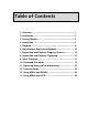
Table of Contents 1. Overview............................................................................ 1 2. Installation......................................................................... 2 3. Getting Started.................................................................. 4 4. Acquisition ........................................................................ 5 5. Playback ............................................................................ 8 6. Simultaneous Acquisition/Playback .......
1. Overview NIDisktm provides direct-to-disk data acquisition and playback using analog I/O cards from National Instruments. Program capabilities include: • Recording up to 8 input channels at up to 1.5 MHz aggregate sample rate • Playback of 1 or 2 channels at up to 1.
NIDisk User Guide • Read file segments into SIGNAL for precision display and measurement NIDisk does not require SIGNAL in order to operate - it can be installed on any Windows 2000/XP computer for stand-alone data acquisition. NIDisk supports all current analog I/O cards manufactured by National Instruments (NI) (www.ni.com). These include PCI desktop cards providing 12-bit and 16-bit resolution at sample rates up to 1.
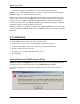
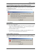
NIDisk User Guide Install NI-DAQmx System Driver and Configure I/O Card NIDisk 3.0 requires NI-DAQmx 8.0 or later. Instructions for downloading and installing the NI-DAQmx system driver and configuring the I/O card are provided in Appendix C of the SIGNAL Reference Guide. If no NI-DAQ system driver is installed, the NIDisk installer will issue the following message. Install NIDisk Follow these steps to install NIDisk. 1. Launch the file nidisk_xxx_setup.
NIDisk User Guide NIDisk User Guide The NIDisk User Guide (this document) is installed as a PDF (Portable Document Format) file in the \docs directory under the SIGNAL root directory (normally c:\Program Files\Engineering Design\Signal 4.0). PDF files require the Acrobat Reader program from Adobe Corporation for viewing. If not already installed, this program is available for free download at http://www.adobe.com/products/acrobat/readstep.html.
NIDisk User Guide 4. Acquisition Performing Acquisition To perform an acquisition, select I/O | Acquire on the NIDisk menu. NIDisk displays the Acquisition parameter screen, which allows the user to configure the acquisition. NIDisk then displays the Acquisition summary screen, which summarizes acquisition parameters and allows the user to initiate the acquisition.
NIDisk User Guide Sample rate may be selected from the drop list of available sample rates in Hz or entered manually. Available sample rates vary with the specific I/O card. They are a subset of the submultiples of some fixed frequency, such as 20 MHz for the PCI-6251. Due to this mathematics, the drop list typically displays all available high frequency rates and a subset of the low frequency choices, which are very dense. Gain sets the gain applied to the input signal before digitizing.
NIDisk User Guide Triggering allows the user to initiate acquisition manually by clicking OK [Manual] or by applying an external TTL signal [External], to synchronize with another system. Trigger polarity indicates whether acquisition will begin on a rising [Low to high] or falling [High to low] trigger signal. See "External Trigger" below for discussion. I/O process done produces an alarm sound when the acquisition is done by playing the sound file IoDone.wav. See "Other Functions" for details.
NIDisk User Guide 5. Playback Performing Playback To perform a playback, select I/O | Play on the NIDisk menu. NIDisk displays the Playback parameter screen, which allows the user to configure the playback. NIDisk then displays the Playback summary screen, which summarizes playback parameters and allows the user to initiate the playback. Playback Parameter Screen The Playback parameters screen allows the user to specify the file to be played, triggering mode and optional alarm sounds.
NIDisk User Guide • SIGNAL files are played at their original voltage range, using a conversion factor stored in the SIGNAL file header. • Wave files are played using an assumed voltage range of ±3 Volts (the default for Wave hardware), which may or may not be the original voltage range of the data. To perform a multi-channel playback, submit a multi-channel SIGNAL or Wave sound file. SIGNAL 4.1 is required to write multi-channel SIGNAL files.
NIDisk User Guide 6. Simultaneous Acquisition/Playback About Simultaneous Acquisition/Playback NIDisk can perform simultaneous acquisition and playback when supported by the I/O device. Simultaneous I/O is supported by most high-performance NI cards, including "Eseries" devices (e.g., DAQCard-6062E) and "M-series" devices (e.g., PCI-6251). Applications include synchronized stimulus-response experiments and playbacks adapted dynamically based on vocalization responses acquired during playback.
NIDisk User Guide Acquisition/Playback Parameter Screen The Acquisition/Playback parameter screen allows the user to specify acquisition duration, sample rate, input gain, number of channels, the name or prefix, file type, and channel format of the datafile to receive the acquired data, optional overwrite of pre-existing datafiles, triggering, datafile to be played, and optional alarm sounds. See "Acquisition Parameter Screen" and "Playback Parameter Screen" for a description of these parameters.
NIDisk User Guide Acquisition/Playback Summary Screen After closing the acquisition/playback parameter screen, NIDisk displays a summary of the acquisition/playback parameters, showing the actual sample rate, gain, number of channels, destination filename(s), required disk space, and other information. NIDisk does not check for sufficient disk space before acquiring, so be sure the required space is available on the disk.
NIDisk User Guide During simultaneous acquisition/playback, only the acquisition progress screen is displayed. Elapsed Time Display The meter shows elapsed acquisition or playback time graphically via a real-time linear bar display and numerical readout. See the figures. Headroom Display The meter shows peak signal level graphically via a real-time linear bar display, similar to an LED-based VU meter on a recording console. See the figures.
NIDisk User Guide Here is the meter after recording with low headroom represented by a yellow bar: and here is the meter during an overload condition represented by a red bar: Final Meter Display After recording, the meter reports total headroom, which is the worst-case (minimum) headroom of the signal during the entire recording.
NIDisk User Guide the display. The total headroom value is reflected in both the numerical readout and bar display. 8. Acquisition and Playback Triggering Triggering NIDisk from an External System External triggering allows the user to initiate acquisition or playback in NIDisk via an external control signal, in order to synchronize the NIDisk I/O process with an external system.
NIDisk User Guide 4. Acquisition or playback will begin on receipt of the external trigger signal. Triggering an External System from NIDisk Output triggering allows the user to initiate some process in an external system at the beginning or end of acquisition or playback in NIDisk, in order to synchronize the NIDisk I/O process with an external system. For example, the user can start a playback in NIDisk, then use the output trigger signal to trigger an external neurophysiological data acquisition system.
NIDisk User Guide 9. Other Functions Alarm Sounds NIDisk can produce alarm sounds to alert the user to certain acquisition or playback conditions. These sounds are played through the system sound card, independent of the NIDisk I/O board. Alaram sounds are stored as Wave files in the NIDisk directory (see "Acquisition and Playback" for the filenames). Users can customize any sound by substituting another Wave file of the same name.
NIDisk User Guide (to avoid specifying parameters on the setup screen) and for automation and interfacing with SIGNAL, as described below.
NIDisk User Guide will acquire two channels for 60 seconds at 50 kHz sample rate per channel with a gain multiplier of 10, to a two-channel SIGNAL-format sound file called myAcqFile, while simultaneously playing the sound file myPlayFile. If the filename or filename prefix includes embedded spaces, enclose the entire name in quotation marks, for example: nidisk a 2 60 50000 10 s "\my project\myfile" Calling NIDisk from SIGNAL NIDisk can be called from SIGNAL using the EXEC command.
NIDisk User Guide RA family commands) to determine when the I/O process has completed and whether it was successful. 11. Operating Hints and Troubleshooting Following are operating hints and troubleshooting guidelines for the NIDisk system. None or Obsolete NI-DAQ System Driver Installed NIDisk 3.0 requires NI-DAQmx v8.0 or later. If this version is not installed, NIDisk will issue the following message on startup.
NIDisk User Guide 1. If the I/O device is not present or is not named "Dev1", NIDisk issues the following message: If the device is not present, install it as described in Appendix C of the SIGNAL Reference Guide. If it is present, open Measurement & Automation Explorer (MAX) as described under "Confirm and troubleshoot I/O card and driver installation" in Appendix C and verify that the device is named "Dev1" (see figure). If not, R-click and rename. 2.
NIDisk User Guide 4. If NIDisk has (or may have) terminated abnormally, it may be running as a "phantom" process and preventing other NIDisk processes from operating correctly. To check this in Windows XP, open Windows Task Manager by hitting Ctrl-Alt-Del, select the Processes tab, and click Image Name to view the task names in alphabetical order. Select each "nidisk.exe" task and click End Process to terminate it. Then launch NIDisk again.
NIDisk User Guide Disk Fragmentation and Maximum Sample Rate On older hard disks, fragmentation can degrade the maximum sample rate. Disks can be defragmented by clicking My Computer | Local Disk | Properties | Tools | Defragment Now. This process should be performed with care, and a full backup is recommended before degragmenting. Notebook Power Management Some notebook computers (such Toshiba models) optionally reduce processor speed when running from batteries, to conserve battery life.
NIDisk User Guide select the Power Save Mode tab, and move the 4 slider controls associated with Processor Speed to Full, 4) click OK. Running the PCMCIA Card from a Desktop Computer A PCMCIA card can be run from a desktop computer using a PCMCIA to PCI adapter card. This card costs approximately $200 and can allow the card to do "double duty", for example, in a desktop workstation in the lab and in a notebook computer in the field. Contact Engineering Design for the currently recommended adapter.
NIDisk User Guide Minimum sample rate Maximum sample rate Programmable gain 100 Hz 500 kHz 1, 2, 5, 10, 20, 50, 100 Impedance Noise (re max signal level) THD 100 G-ohm in parallel with 100 pF n/s n/s Output characteristics Maximum channels Minimum sample rate Maximum sample rate Impedance Noise (re max signal level) THD Input/output characteristics No. sample rates Maximum signal level Maximum signal length 2 100 Hz 500 kHz < 0.
NIDisk User Guide the input signal is V(t) = A sin 2πft, then voltage change is dV/dt = 2πfA cos 2πft, whose maximum = 2πfA Volts/sec. So instantaneous voltage change depends on the product of input amplitude (A) and frequency (f) and will be greatest for a full-scale input signal of maximum (Nyquist) frequency. Under these worst-case conditions, and for input gains between 1 and 10, NI-specified settling time is 1 usec to 12 bit accuracy and 1.5 usec to 16 bit accuracy.
NIDisk User Guide • SIGNAL can display the entire sound file (see below), which the researcher can use as a roadmap to extract specific sound events. SIGNAL can manually extract, display, measure, and analyze these events and store them as individual sound files. SIGNAL can also be programmed to perform acoustic measurements automatically on the stored events.
NIDisk User Guide spectrogram with typically 30-60 seconds of sound per screen. This allows the user to navigate through a long recording, spotting sound events and extracting them for detailed analysis. Settings such as frequency range and spectrogram resolution can be used to customize the display. Note: STRIP settings can be collected in a SIGNAL macro for convenience. 5. After using STRIP to review the sound file and locate vocalization events, read individual events into SIGNAL using the R /Q command.
NIDisk User Guide The wide screen and high-resolution spectrogram of the RTS can be used to locate events in sparse data sets. For example, the sparse sound file in the following figure was displayed in 5-minute segments, in which the 3 events are clearly visible. With 3 seconds to draw or scroll a new screen, this allows sparse data sets to be analyzed at 100 times real-time. Once located, individual events can be zoomed for close examination.
NIDisk User Guide The RTS runs within SIGNAL, so sound segments can be transferred easily to SIGNAL buffers for immediate analysis, and measured sound parameters can be stored in the SIGNAL logfile. In the following figure, the RTS has saved 6 events in SIGNAL buffers and 11 measurement records have been stored in the SIGNAL logfile. Events can also be stored as SIGNAL, Wave, or AIFF sound files for later analysis.